Authorized Service

For GE parts and service, call: 773 299-6600

Table of Contents

Page

Introduction . . . . . . . . . . . . . . . . . . . . . . . . . . . . . . . . ii Safety . . . . . . . . . . . . . . . . . . . . . . . . . . . . . . . . . . . . . .11 Equipment Inspection and Storage . . . . . . . . . .11 Final Equipment Inspection . . . . . . . . . . . . . . .11 Mounting . . . . . . . . . . . . . . . . . . . . . . . . . . . . . . .11 Installation . . . . . . . . . . . . . . . . . . . . . . . . . . . . . . . . . .12 Power Connections . . . . . . . . . . . . . . . . . . . . . . .12 Engine Start Control Connections . . . . . . . . .12-3 Initial Energization . . . . . . . . . . . . . . . . . . . . .13-4 Control Connections . . . . . . . . . . . . . . . . . . . . . 5 Entelli-Switch 250 Microprocessor Controller . . . . .16 Overview . . . . . . . . . . . . . . . . . . . . . . . . . . . . . . .16 LCD & Keypad . . . . . . . . . . . . . . . . . . . . . . . . . .17 User Setting for Voltage & Frequency . . . . . . .1 8 Accessory Group Packages. . . . . . . . . . . . . . . . . 9 Accessory Definitions . . . . . . . . . . . . . . . . . . 10-13 How to Set the System Clock . . . . . . . . . . . . . . 13 CDT One Event Timer Exerciser . . . . . . . . . . 14 CDP Clock Exerciser . . . . . . . . . . . . . . . . . . . . 15 User Setup - CFG Menu . . . . . . . . . . . . . . . . . . 16 User Setup - SET Menu . . . . . . . . . . . . . . . . . . 17 User Setup - System Info . . . . . . . . . . . . . . . . . 18 Bypass-Isolation Operation . . . . . . . . . . . . . . . . . . .121 100-400 Amps . . . . . . . . . . . . . . . . . . . . . . . . . .122 600-1200 Amps . . . . . . . . . . . . . . . . . . . . . . . . .123 1600-4000 Amps . . . . . . . . . . . . . . . . . . . . . . . .1 24

Page

Testing . . . . . . . . . . . . . . . . . . . . . . . . . . . . . . . . . . . .119

ATS Testing . . . . . . . . . . . . . . . . . . . . . . . . . . . .119

Standard Transition . . . . . . . . . . . . . . . . . . . . . 19

Delayed Transition . . . . . . . . . . . . . . . . . . . . . . 19

Sequence of Operation . . . . . . . . . . . . . . . . . . . . . . 20

Standard Transition . . . . . . . . . . . . . . . . . . . . .120

Delayed Transition . . . . . . . . . . . . . . . . . . . . . . 20

Controls Power Supply (CPS) . . . . . . . . . . . . . . . . . 21

Schematics, Standard & Delay . . . . . . . . . . . . .122

Troubleshooting & Diagnostics . . . . . . . . . . . . . . . . 23

Maintenance and Testing . . . . . . . . . . . . . . . . . . . . . 24

Inspection and Cleaning . . . . . . . . . . . . . . . . . 24

Servicing . . . . . . . . . . . . . . . . . . . . . . . . . . . . . .124

Testing . . . . . . . . . . . . . . . . . . . . . . . . . . . . . . . .124

ZBTSH/ZBTSDH . . . . . . . . . . . . . . . . . . . . . . . . . . . 25

Standard Control Panel Layout (SSRCP) . . . . 25

Panel Mount Control Relays . . . . . . . . . . . . . .125

Sequence of Operation . . . . . . . . . . . . . . . . . . . . . . 26

Adjustments and Settings . . . . . . . . . . . . . . . . . . . . . 27

Solid State Timers . . . . . . . . . . . . . . . . . . . . . . .127

Voltage/Frequency Sensor (VSFM) . . . . . . . . .127

Solid State Phase Relay . . . . . . . . . . . . . . . . . . .127

Introduction

GE Zenith Transfer Switches are used to provide a continuous source of power for lighting and other critical loads by auto- matically transferring from source 1 power to source 2 power in the event that source 1 voltage falls below preset limits.

Voltage sensing and system control is performed via a state-of-the-art microcontroller located on the cabinet door. It is designed to give highly accurate control of the transfer switch system.

All GE Zenith transfer switches are designed for use on emergency or standby systems, and are rated for total system or motor loads. Transfer switches are UL Listed under Standard 1008 and CSA Certified under Standard C22.2 No. 178 and IEC Listed under Standard 947.

NOTES:

A protective device such as a molded case circuit breaker or fused disconnect switch MUST be installed on both sources of incoming power for circuit protection and as a disconnection device.

All references made within this manual about the term “S1” or “Source 1” relate to a Normal Power Source.

All references made about the term “S2” or “Source 2” relate to an Emergency or Alternative Power Source.

Page 2
Image 2
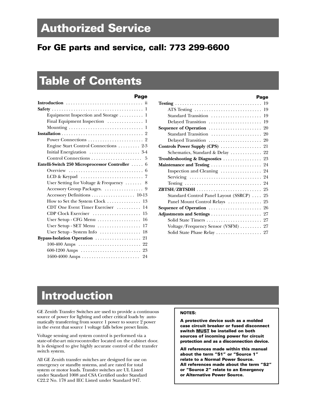
GE ZBTSD manual Authorized Service, Table of Contents, Introduction

ZBTS, ZBTSD specifications

General Electric (GE) has established itself as a leader in the field of industrial automation and control systems, with its ZBTSD and ZBTS series representing some of the most advanced technology available. These systems are engineered to enhance performance, efficiency, and reliability in various industrial applications.

The ZBTSD, or Zero-Based Time Series Data, is designed to optimize data storage and retrieval processes. One of its main features is its ability to provide real-time monitoring and analytics of dynamic processes. This capability is crucial for industries that require immediate insights into their operations, helping to minimize downtime and enhance decision-making. The ZBTSD utilizes advanced machine learning algorithms to identify trends and patterns, enabling predictive maintenance that can significantly reduce operational costs.

On the other hand, the ZBTS, or Zero-Based Time Series Solutions, focuses on delivering comprehensive solutions for time series data management. This system is adept at handling vast amounts of data generated by industrial equipment, ensuring that organizations can efficiently process and analyze this information. Key characteristics of ZBTS include scalability, which allows companies to expand their systems as their data grows, and flexibility, permitting integration with various data sources.

One notable technology employed in both ZBTSD and ZBTS is cloud computing. By leveraging the cloud, these systems offer enhanced data accessibility and collaboration capabilities. Users can access critical data anytime, anywhere, facilitating timely responses to operational challenges.

Another significant feature is robust cybersecurity measures. With the increasing number of cyber threats in industrial environments, GE has prioritized security in the ZBTSD and ZBTS systems. These solutions are equipped with advanced encryption protocols and user authentication mechanisms to protect sensitive data from unauthorized access.

The user interface of both systems is designed to be intuitive, allowing operators to interact with the systems efficiently. Customizable dashboards provide visual representations of key performance indicators, making it easier for users to comprehend complex data at a glance.

In summary, GE's ZBTSD and ZBTS systems exemplify the integration of cutting-edge technology in industrial automation. Their emphasis on real-time data analytics, scalability, cybersecurity, and user-friendly design positions them as invaluable tools for organizations seeking to enhance operational efficiency and decision-making. As industries continue to evolve, these systems will play a pivotal role in shaping the future of industrial automation and data management.