INSTALLATION INSTRUCTIONS
3/4″ ![]()
![]()
1/4″ O.D. water line compression fitting at water valve
71/2″
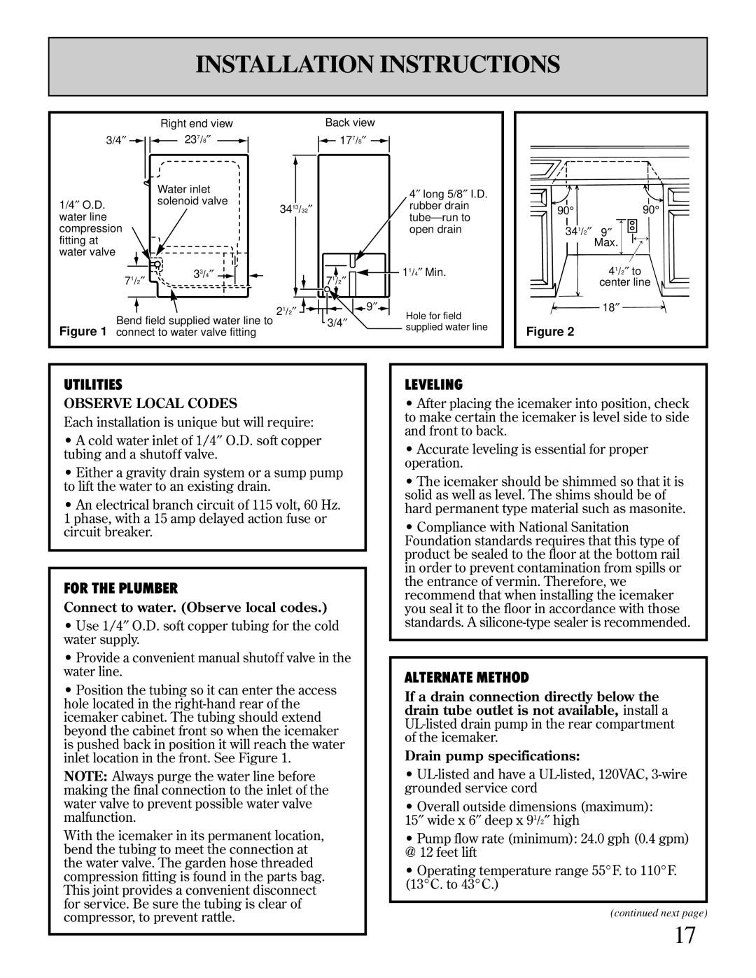
Right end view 237/8″
Water inlet solenoid valve
33/4″
Back view ![]() 177/8″
177/8″ ![]()
![]()
4″ long 5/8″ I.D.
3413/32″rubber drain
open drain
|
|
|
|
|
|
|
|
| 71/2″ |
|
|
|
|
|
|
|
|
|
| 11/4″ Min. | |
|
|
|
|
|
|
|
|
|
|
|
|
|
|
| |||||||
|
|
|
|
|
|
|
|
|
|
|
|
|
|
|
|
|
|
| |||
|
|
|
|
|
|
|
|
|
|
|
|
|
|
|
| 9″ |
|
|
|
| |
21/2″ |
|
|
|
|
|
|
|
|
|
|
|
|
|
|
|
|
| Hole for field | |||
|
|
|
|
|
|
|
|
|
|
|
|
|
|
|
| ||||||
|
|
|
|
|
|
|
|
|
|
|
|
|
|
|
|
|
|
| |||
90° | 90° |
341/2″ 9″ | |
| Max. |
| 41/2″ to |
| center line |
| 18″ |
Bend field supplied water line to Figure 1 connect to water valve fitting
3/4″ | supplied water line |
|
Figure 2 |
UTILITIES
OBSERVE LOCAL CODES
Each installation is unique but will require:
•A cold water inlet of 1/4″ O.D. soft copper tubing and a shutoff valve.
•Either a gravity drain system or a sump pump to lift the water to an existing drain.
•An electrical branch circuit of 115 volt, 60 Hz.
1 phase, with a 15 amp delayed action fuse or circuit breaker.
FOR THE PLUMBER
Connect to water. (Observe local codes.)
•Use 1/4″ O.D. soft copper tubing for the cold water supply.
•Provide a convenient manual shutoff valve in the water line.
•Position the tubing so it can enter the access hole located in the
NOTE: Always purge the water line before making the final connection to the inlet of the water valve to prevent possible water valve malfunction.
With the icemaker in its permanent location, bend the tubing to meet the connection at the water valve. The garden hose threaded compression fitting is found in the parts bag. This joint provides a convenient disconnect for service. Be sure the tubing is clear of compressor, to prevent rattle.
LEVELING
•After placing the icemaker into position, check to make certain the icemaker is level side to side and front to back.
•Accurate leveling is essential for proper operation.
•The icemaker should be shimmed so that it is solid as well as level. The shims should be of hard permanent type material such as masonite.
•Compliance with National Sanitation Foundation standards requires that this type of product be sealed to the floor at the bottom rail in order to prevent contamination from spills or the entrance of vermin. Therefore, we recommend that when installing the icemaker you seal it to the floor in accordance with those standards. A
ALTERNATE METHOD
If a drain connection directly below the drain tube outlet is not available, install a
Drain pump specifications:
•
•Overall outside dimensions (maximum):
″wide x 6″ deep x 91/2″ high15
•Pump flow rate (minimum): 24.0 gph (0.4 gpm) @ 12 feet lift
•Operating temperature range 55°F. to 110°F. (13°C. to 43°C.)
(continued next page)
17