DIP SWITCH CONFIGURATION
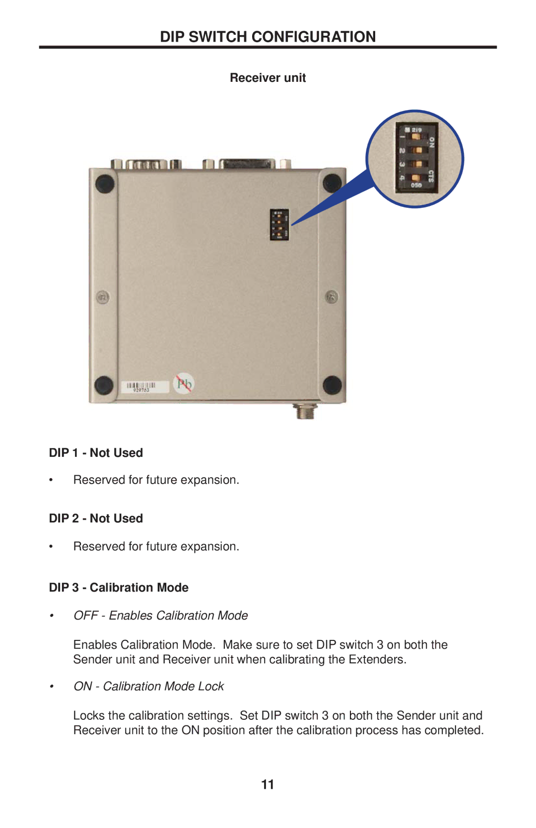
Receiver unit
DIP 1 - Not Used
•Reserved for future expansion.
DIP 2 - Not Used
•Reserved for future expansion.
DIP 3 - Calibration Mode
•OFF - Enables Calibration Mode
Enables Calibration Mode. Make sure to set DIP switch 3 on both the Sender unit and Receiver unit when calibrating the Extenders.
•ON - Calibration Mode Lock
Locks the calibration settings. Set DIP switch 3 on both the Sender unit and Receiver unit to the ON position after the calibration process has completed.
11
