POWER SYSTEMS
POWER SYSTEMS, INC
DEADLY EXHAUST FUMES. OUTDOOR INSTALLATION ONLY
DANGER
DANGER
INTRODUCTION
AUTHORIZED DEALER LOCATION
‹CONTENTS
Introduction
Parts of the generator are rotating and/or hot
GENERAL HAZARDS
Despite the safe design of this generator
EXPLOSION HAZARDS
ELECTRICAL HAZARDS
FIRE HAZARDS
‹STANDARDS INDEX
1.3SYSTEM SET LED
1.1UNPACKING/INSPECTION
1.2PROTECTION SYSTEMS
Figure 1.2 - 12 kW and 15 kW, V-twin GT-990Engine
1.4YOUR GENERATOR
Figure 1.1 - 7 kW, Single Cylinder GH-410Engine
‹1.5.2 ENGINE
1.5 SPECIFICATIONS
‹ 1.5.1 GENERATOR
1.7FUEL CONSUMPTION
1.8RECONFIGURING THE FUEL SYSTEM
1.6FUEL REQUIREMENTS AND RECOMMENDATIONS
DANGER
1.9.2 TRANSFER SWITCH
1.10 BATTERY INSTALLATION
1.9LOCATION
1.9.1 GENERATOR
Wear rubber gloves and boots
1.11 THE BATTERY
Figure 1.5 - Battery Cable Connections
Do not open or mutilate the battery. Released
2.3ELECTRICAL CHECKS
2.2CHECK TRANSFER SWITCH OPERATION
2.1BEFORE INITIAL START-UP
Never operate the engine with the oil level
2.5CHECKING AUTOMATIC OPERATION
2.6ADJUSTING THE REGULATOR NATURAL GAS ONLY
2.4GENERATOR TESTS UNDER LOAD
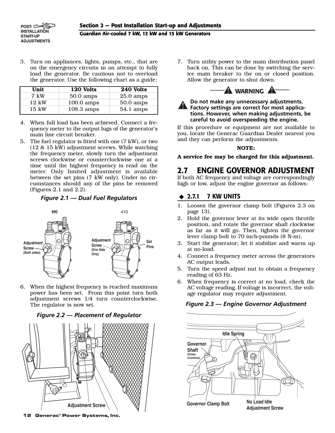
Figure 2.3 - Engine Governor Adjustment
2.7ENGINE GOVERNOR ADJUSTMENT
Figure 2.2 - Placement of Regulator
Do not make any unnecessary adjustments
Figure 2.4 - Full Load Speed Adjust Screw
2.8VOLTAGE REGULATOR ADJUSTMENT
3.1BREAK-INPROCEDURE
Figure 2.5 - Voltage Adjustment Potentiometer
With the switch set to AUTO, the engine may
3.3AUTOMATIC TRANSFER OPERATION
3.2USING THE AUTO/OFF/MANUAL SWITCH FIGURE
3.4SEQUENCE OF AUTOMATIC OPERATION
‹3.5.2 TRANSFER BACK TO UTILITY POWER SOURCE
3.6SETTING THE EXERCISE TIMER
3.5MANUAL TRANSFER OPERATION
Figure 3.2 - Manual Transfer Switch Operation
‹3.7.1 LOW OIL PRESSURE SWITCH
3.7PROTECTION SYSTEMS
4.1FUSE
‹3.7.2 HIGH TEMPERATURE SWITCH
‹ 4.3.2 OIL CHANGE PROCEDURE
4.2CHECKING THE ENGINE OIL LEVEL
4.3CHANGING THE ENGINE OIL
‹4.3.1 ENGINE OIL RECOMMENDATIONS
4.6SPARK PLUGS
4.5CHANGING THE ENGINE AIR CLEANER
4.4CHANGING THE OIL FILTER
Figure 4.6 - 7 kW, Engine Air Cleaner Location
Figure 4.8 - Setting the Spark Plug Gap
4.7BATTERY MAINTENANCE
4.8ADJUSTING GH-410/GT-990VALVE CLEARANCE
4.11 CORROSION PROTECTION
4.9COOLING SYSTEM
4.10 ATTENTION AFTER SUBMERSION
Figure 4.10 - Valve Clearance Adjustment
‹4.12.2 RETURN TO SERVICE
4.12 OUT OF SERVICE PROCEDURE
‹4.12.1 REMOVAL FROM SERVICE
4.13 SERVICE SCHEDULE
CAUSE
5.1TROUBLESHOOTING GUIDE
PROBLEM
CORRECTION
24 Generac Power Systems, Inc
Section 6 - Electrical Data
CONNECTION
CONTROL PANEL BOX
CUSTOMER
26 Generac Power Systems, Inc
C2-6
Wiring Diagram - 7 kW - Drawing No. 0D9013-A
28 Generac Power Systems, Inc
CUSTOMER CONNECTION
CLOSEST TO BEA 4 0 STATOR
30 Generac Power Systems, Inc
C2-6
Section 7 - Exploded Views and Parts Lists
32 Generac Power Systems, Inc
PART NO.QTY. DESCRIPTION
Control Panel - Drawing No. 0D8503-E
DESCRIPTION
Section 7 - Exploded Views and Parts Lists
0D4801
37 17 24
0D3086
Kit Contains
DESCRIPTION
42 Generac Power Systems, Inc
DESCRIPTION
44 Generac Power Systems, Inc
7 kW Generator - Drawing No. 0D3504-B
46 Generac Power Systems, Inc
12 kW and 15 kW Generator - Drawing No. 0D3417-B
48 Generac Power Systems, Inc
GN410 Engine - Drawing No. 0D3539-BPart
50 Generac Power Systems, Inc
0C1069
PART NO. QTY
Guardian Air
Section 8 - Mounting Dimensions
TRANSFER SWITCH
NTAKE
54 Generac Power Systems, Inc
Generac Power Systems, Inc
PURCHASER’S/OWNER’S WARRANTY RESPONSIBILITIES
CALIFORNIA EMISSION CONTROL WARRANTY STATEMENT
YOUR WARRANTY RIGHTS AND OBLIGATIONS
Section 10 - Warranty
EMISSION CONTROL SYSTEM WARRANTY
EMISSION RELATED PARTS INCLUDE THE FOLLOWING
P.O. BOX WHITEWATER, WI
WARRANTY SCHEDULE
GENERAC POWER SYSTEMS, INC