Section 6 — Electrical Data

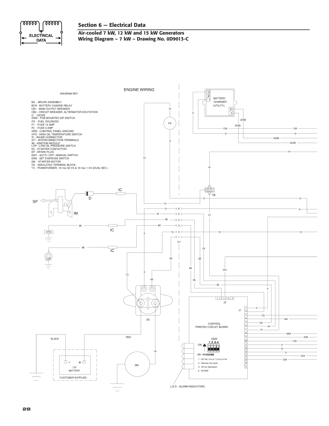
Air-cooled 7 kW, 12 kW and 15 kW Generators Wiring Diagram – 7 kW – Drawing No. 0D9013-C


ENGINE WIRING

DIAGRAM KEY


BA - BRUSH ASSEMBLY


BCR - BATTERY CHARGE RELAY


CB1 - MAIN OUTPUT BREAKER

14

CB2 - CIRCUIT BREAKER, ALTERNATOR EXCITATION


D - DIODE


DSW - PCB MOUNTED DIP SWITCH


FS - FUEL SOLENOID

FS

F1 - FUSE 15 AMP


F2 - FUSE 5 AMP


GRD - CONTROL PANEL GROUND


HTO - HIGH OIL TEMPERATURE SWITCH


IC - INLINE CONNECTOR


ICT - INTERCONNECTION TERMINALS

0

IM - IGNITION MODULE


LOP - LOW OIL PRESSURE SWITCH


SC - STARTER CONTACTOR


SP - SPARK PLUG


SW1 - AUTO / OFF / MANUAL SWITCH

14

SW2 - SET EXERCISE SWITCH

SM - STARTER MOTOR


TB - INSULATED TERMINAL BLOCK

TX - TRANSFORMER, 16 Vac 56 VA & 16 Vac 1 VA (DUAL SEC.)

3

1

0

14

BATTERY CHARGER (UTILITY)


2


1


225B


224B

13A


13A

0

0


225B


224B


14


IC


SP

D


0


14


0

6


IM

18

5

14


85

4


85

86

3


HTO


IC

13 2

13


0


1


C1


86

IC


18


56

56


LOP


86


351


0


13


56


85


56


1


2


4


5


3


J2


J1


SC


CONTROL


PRINTED CIRCUIT BOARD


BLACK


RED


DSW


ON


16


+


1 - 20 Vac Sense Transformer


SM


2 - Remote Not Auto


12V


3 - 50 Hz Operation


BATTERY


4 - SPARE


CUSTOMER SUPPLIED

L.E.D - ALARM INDICATORS

4

1

4

2


3

23

5

56


18

7

14

9


11


13


14


15


16


17


0

0

13

194

66A

239

15A

17

15

0

225

224

28

Page 30
Image 30
Generac 04673-2, 04675-3, 04674-2 owner manual Battery Charger Utility

04674-2, 04675-3, 04673-2 specifications

Generac, a prominent name in the power equipment sector, offers a range of reliable and efficient energy solutions, including the models Generac 04673-2, 04675-3, and 04674-2. These models are designed to meet diverse consumer needs, from residential applications to larger commercial setups, providing dependable backup power during outages.

The Generac 04673-2 is a standout home standby generator specifically engineered for residential use. It boasts an automatic operation feature, ensuring that power is restored within seconds of an outage. This model operates on a robust Generac engine, delivering a reliable power output that can support essential household appliances and systems, including HVAC units, refrigerators, and sump pumps. One of the main characteristics of this generator is its Quiet Test mode, which runs at a lower RPM to minimize noise while conducting weekly self-tests, ensuring that the system is always ready when needed.

Moving on to the Generac 04675-3, this model offers enhanced features tailored for users needing higher power output. With a larger capacity, it can handle more demanding power needs, making it suitable for larger homes or small businesses. The 04675-3 is equipped with advanced technologies, including the Mobile Linkā„¢ remote monitoring system, which enables users to check the status and performance of their generator from anywhere using a smartphone or computer. This connectivity empowers users with real-time information and alerts regarding their generator's operational performance.

The Generac 04674-2 model rounds out the trio, engineered for those who need a powerful standby generator with a slightly different configuration. It features the same robust engine as the other models, ensuring reliability and user-friendly operation. Its standout feature is the integrated transfer switch capability, which allows for seamless transfer of power from the grid to the generator without manual intervention. This model also supports various fuel types, providing flexibility depending on user preference and availability.

All three Generac models focus on safety and efficiency, incorporating features such as excellent ventilation systems, all-weather enclosures, and user-friendly control panels. They are designed for low maintenance, ensuring long-lasting performance without extensive upkeep. With Generac's commitment to innovation and quality, these generators offer peace of mind, enabling users to maintain their lifestyles and operations without interruption during power outages. Whether for home or business use, the Generac 04673-2, 04675-3, and 04674-2 models represent a reliable choice in emergency power solutions.