Section 1 — General Information

Guardian Air-cooled 7 kW, 12 kW and 15 kW Generators

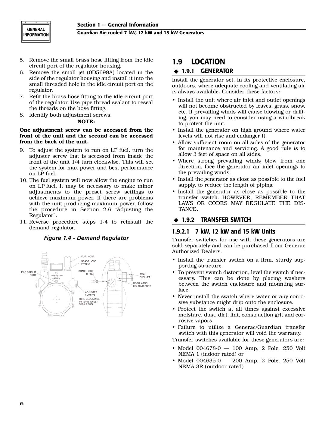
5.Remove the small brass hose fitting from the idle circuit port of the regulator housing.

6.Remove the small jet (0D5698A) located in the side of the regulator housing and install it into the small threaded hole in the idle circuit port on the regulator.

7.Refit the brass hose fitting to the idle circuit port of the regulator. Use pipe thread sealant to reseal the threads on the hose fitting.

8.Identify both adjustment screws.

NOTE:

One adjustment screw can be accessed from the front of the unit and the second can be accessed from the back of the unit.

9.To adjust the system to run on LP fuel, turn the adjuster screw that is accessed from inside the front of the unit 1/4 turn clockwise. This will set the system for max power and best performance on LP fuel.

10.The fuel system will now allow the engine to run on LP fuel. It may be necessary to make minor adjustments to the preset screw settings to achieve maximum power. If there are problems with the unit producing maximum power, follow the procedure in Section 2.6 “Adjusting the Regulator”.

11.Reverse procedure steps 1-4 to reinstall the demand regulator.

1.9LOCATION

1.9.1 GENERATOR

Install the generator set, in its protective enclosure, outdoors, where adequate cooling and ventilating air is always available. Consider these factors:

Install the unit where air inlet and outlet openings will not become obstructed by leaves, grass, snow, etc. If prevailing winds will cause blowing or drift- ing, you may need to consider using a windbreak to protect the unit.

Install the generator on high ground where water levels will not rise and endanger it.

Allow sufficient room on all sides of the generator for maintenance and servicing. A good rule is to allow 3 feet of space on all sides.

Where strong prevailing winds blow from one direction, face the generator air inlet openings to the prevailing winds.

Install the generator as close as possible to the fuel supply, to reduce the length of piping.

Install the generator as close as possible to the transfer switch. HOWEVER, REMEMBER THAT LAWS OR CODES MAY REGULATE THE DIS- TANCE.

1.9.2 TRANSFER SWITCH

1.9.2.1 7 kW, 12 kW and 15 kW Units

Figure 1.4 - Demand Regulator

Transfer switches for use with these generators are sold separately and can be purchased from Generac Authorized Dealers.

IDLE CIRCUIT PORT


FUEL HOSE


BRASS HOSE


FITTING

O

BRASS HOSE

FITTING

U

T

PRESSURE

1

TAP


1/8 NPT


ADJUSTER


SCREWS


TURN CLOCKWISE


1/4 TURN TO SET


FOR LP FUEL.

SMALL

FUEL JET

REGULATOR HOUSING PORT

Install the transfer switch on a firm, sturdy sup- porting structure.

To prevent switch distortion, level the switch if nec- essary. This can be done by placing washers between the switch enclosure and mounting sur- face.

Never install the switch where water or any corro- sive substance might drip onto the enclosure.

Protect the switch at all times against excessive moisture, dust, dirt, lint, construction grit and cor- rosive vapors.

Failure to utilize a Generac/Guardian transfer switch with this generator will void the warranty.

Transfer switches available for these generators are:

Model 004678-0 — 100 Amp, 2 Pole, 250 Volt NEMA 1 (indoor rated) or

Model 004635-0 — 200 Amp, 2 Pole, 250 Volt NEMA 3R (outdoor rated)

8

Page 10
Image 10
Generac Power Systems 04759-0, 04758-0, 04760-0 Location, Generator, Transfer Switch, 2.1 7 kW, 12 kW and 15 kW Units

04760-0, 04759-0, 04758-0 specifications

Generac Power Systems is a leading manufacturer in the field of power generation, known for its innovative products that cater to both residential and commercial customers. Among its prominent offerings, the Generac models 04758-0, 04759-0, and 04760-0 stand out as essential solutions for backup energy needs. These units offer reliable power during outages, ensuring that homes and businesses remain operational regardless of external conditions.

The Generac 04758-0 is a robust standby generator designed for residential use. Featuring a powerful engine, it delivers a dependable power output when it is needed most. Key characteristics include an automatic transfer switch that detects power loss and activates the generator without user intervention. This means that homeowners can enjoy peace of mind knowing that their essential appliances and systems will continue to function seamlessly during outages. Additionally, its compact design allows for easy installation in most home settings.

Moving on to the Generac 04759-0, this model offers even greater power capacity, making it suitable for larger homes or small businesses. It incorporates advanced technologies such as digital power management, which optimizes fuel efficiency and reduces emissions. The O47-59-0 is also known for its durable construction, providing reliable performance in various weather conditions. Its user-friendly interface allows for straightforward operation and monitoring, ensuring users remain informed about their power status.

The Generac 04760-0 takes it a step further by enhancing its overall performance with innovations in noise reduction and fuel consumption. It is engineered with a leading-edge cooling system that minimizes operational noise, making it ideal for residential neighborhoods where sound regulations are a concern. This model is also compatible with a variety of fuels, giving users flexibility based on availability and cost. Its comprehensive warranty further underscores Generac's commitment to customer satisfaction and product reliability.

In summary, the Generac Power Systems models 04758-0, 04759-0, and 04760-0 exemplify technology and engineering excellence in the power generation industry. With features designed for efficiency, durability, and user convenience, these models provide steadfast support to users seeking dependable backup power solutions. Whether for a home or small business, Generac's offerings remain a trusted choice for managing unexpected power outages.