Section 3 — Operation

Guardian Air-cooled 7 kW, 12 kW and 15 kW Generators

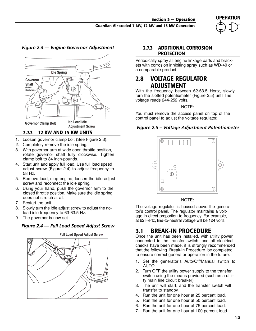
Figure 2.3 — Engine Governor Adjustment

Idle Spring

Governor

Shaft

(Rotate

Clockwise)

Governor Clamp Bolt

No Load Idle

Adjustment Screw


2.7.2 12 KW AND 15 KW UNITS

1.Loosen governor clamp bolt (See Figure 2.3).

2.Completely remove the idle spring.

3.With governor arm at wide open throttle position, rotate governor shaft fully clockwise. Tighten clamp bolt to 84 inch-pounds.

4.Start unit and apply full load. Use full load speed adjust screw (Figure 2.4) to adjust frequency to 58 Hz.

5.Remove load, stop engine, loosen the idle adjust screw and reconnect the idle spring.

6.Using your hand, push the governor arm to the closed throttle position. Make sure the idle spring does not stretch at all.

7.Restart the unit.

8.Slowly turn the idle adjust screw to adjust the no- load idle frequency to 63-63.5 Hz.

9.The governor is now set.

2.7.3 ADDITIONAL CORROSION PROTECTION

Periodically spray all engine linkage parts and brack- ets with corrosion inhibiting spray such as WD-40 or a comparable product.

2.8VOLTAGE REGULATOR

ADJUSTMENT

With the frequency between 62-63.5 Hertz, slowly turn the slotted potentiometer (Figure 2.5) until line voltage reads 244-252 volts.

NOTE:

You must remove the access panel on top of the control panel to adjust the voltage regulator.

Figure 2.5 – Voltage Adjustment Potentiometer

NOTE:

The voltage regulator is housed above the genera- tor's control panel. The regulator maintains a volt- age in direct proportion to frequency. For example, at 62 Hertz, line-to-neutral voltage will be 124 volts.

Figure 2.4 — Full Load Speed Adjust Screw

Full Load Speed Adjust Screw

3.1BREAK-IN PROCEDURE

Once the unit has been installed, with utility power connected to the transfer switch, and all electrical checks have been made, it is strongly recommended that the following “Break-in Procedure” be completed to ensure correct generator operation in the future.

1.Set the generator’s Auto/Off/Manual switch to AUTO.

2.Turn OFF the utility power supply to the transfer switch using the means provided (such as a utili- ty main line circuit breaker).

3.The unit will start, and the transfer switch will transfer to standby.

4.Run the unit for one hour at 25 percent load.

5.Run the unit for one hour at 50 percent load.

6.Run the unit for one hour at 75 percent load.

7.Run the unit for one hour at 100 percent load.

13

Page 15
Image 15
Generac Power Systems 04758-0, 04759-0, 04760-0 Voltage Regulator Adjustment, BREAK-IN Procedure, 2 12 KW and 15 KW Units

04760-0, 04759-0, 04758-0 specifications

Generac Power Systems is a leading manufacturer in the field of power generation, known for its innovative products that cater to both residential and commercial customers. Among its prominent offerings, the Generac models 04758-0, 04759-0, and 04760-0 stand out as essential solutions for backup energy needs. These units offer reliable power during outages, ensuring that homes and businesses remain operational regardless of external conditions.

The Generac 04758-0 is a robust standby generator designed for residential use. Featuring a powerful engine, it delivers a dependable power output when it is needed most. Key characteristics include an automatic transfer switch that detects power loss and activates the generator without user intervention. This means that homeowners can enjoy peace of mind knowing that their essential appliances and systems will continue to function seamlessly during outages. Additionally, its compact design allows for easy installation in most home settings.

Moving on to the Generac 04759-0, this model offers even greater power capacity, making it suitable for larger homes or small businesses. It incorporates advanced technologies such as digital power management, which optimizes fuel efficiency and reduces emissions. The O47-59-0 is also known for its durable construction, providing reliable performance in various weather conditions. Its user-friendly interface allows for straightforward operation and monitoring, ensuring users remain informed about their power status.

The Generac 04760-0 takes it a step further by enhancing its overall performance with innovations in noise reduction and fuel consumption. It is engineered with a leading-edge cooling system that minimizes operational noise, making it ideal for residential neighborhoods where sound regulations are a concern. This model is also compatible with a variety of fuels, giving users flexibility based on availability and cost. Its comprehensive warranty further underscores Generac's commitment to customer satisfaction and product reliability.

In summary, the Generac Power Systems models 04758-0, 04759-0, and 04760-0 exemplify technology and engineering excellence in the power generation industry. With features designed for efficiency, durability, and user convenience, these models provide steadfast support to users seeking dependable backup power solutions. Whether for a home or small business, Generac's offerings remain a trusted choice for managing unexpected power outages.