General Information
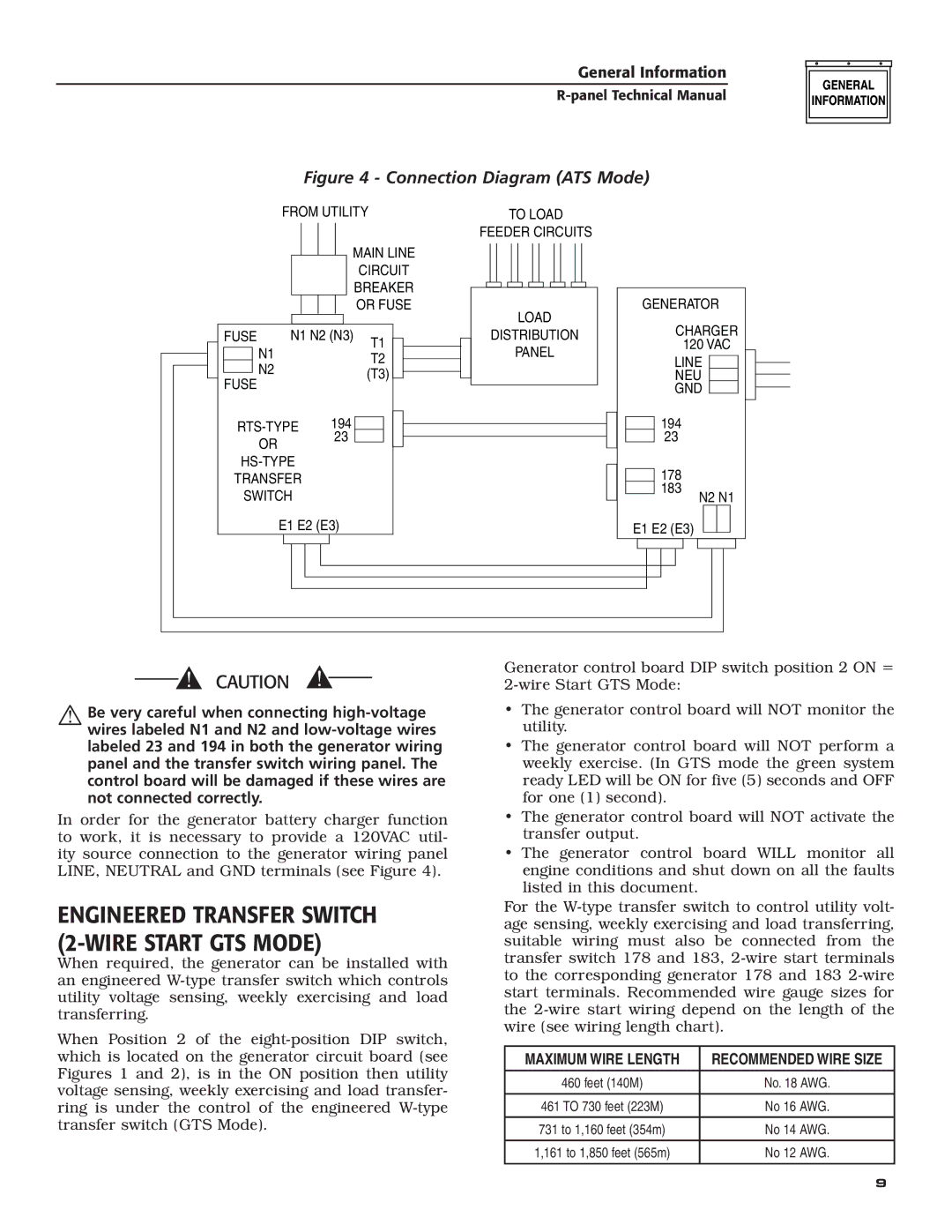
Figure 4 - Connection Diagram (ATS Mode)
|
|
|
| FROM UTILITY |
| |||||||||
|
|
|
|
|
|
|
|
|
| MAIN LINE |
| |||
|
|
|
|
|
|
|
|
|
|
| CIRCUIT |
| ||
|
|
|
|
|
|
|
|
|
|
| BREAKER |
| ||
|
|
|
|
|
|
|
|
|
|
|
| |||
|
|
|
|
|
|
|
|
|
|
| OR FUSE |
| ||
|
|
|
|
|
|
|
|
|
|
|
|
|
|
|
| FUSE | N1 | N1 N2 (N3) | T1 |
|
|
| |||||||
|
|
|
| |||||||||||
|
|
|
|
|
|
|
|
|
| T2 |
|
|
| |
|
|
| N2 |
|
|
|
|
|
|
|
|
|
| |
|
|
|
|
|
|
|
|
|
| (T3) |
|
|
| |
| FUSE |
|
|
|
|
|
|
|
|
|
| |||
|
|
|
|
|
|
|
|
|
|
|
| |||
|
|
|
|
|
|
|
|
|
|
|
|
| ||
OR 23
TRANSFER
SWITCH
E1 E2 (E3)
TO LOAD
FEEDER CIRCUITS
LOAD
DISTRIBUTION
PANEL
GENERATOR
CHARGER
120 VAC
LINE
NEU
GND
194
23
178
183
N2 N1
E1 E2 (E3)
Be very careful when connecting
In order for the generator battery charger function to work, it is necessary to provide a 120VAC util- ity source connection to the generator wiring panel LINE, NEUTRAL and GND terminals (see Figure 4).
ENGINEERED TRANSFER SWITCH (2-WIRE START GTS MODE)
When required, the generator can be installed with an engineered
When Position 2 of the
Generator control board DIP switch position 2 ON =
•The generator control board will NOT monitor the utility.
•The generator control board will NOT perform a weekly exercise. (In GTS mode the green system ready LED will be ON for five (5) seconds and OFF for one (1) second).
•The generator control board will NOT activate the transfer output.
•The generator control board WILL monitor all engine conditions and shut down on all the faults listed in this document.
For the
MAXIMUM WIRE LENGTH | RECOMMENDED WIRE SIZE |
|
|
460 feet (140M) | No. 18 AWG. |
|
|
461 TO 730 feet (223M) | No 16 AWG. |
|
|
731 to 1,160 feet (354m) | No 14 AWG. |
|
|
1,161 to 1,850 feet (565m) | No 12 AWG. |
|
|
9