III.The indicator signal chart:
| Signal | Condition | |
|
|
| |
User Signals | Yellow | Power on, | |
Green | Lock relay active | ||
| Red | Invalid Card | |
| Yellow、Green Flashing | The memory is empty | |
| Green Flashing | Into the ADD CARDS MODE | |
Programming | Red Flashing | Into the DELETE CARDS MODE | |
Yellow、Red Flashing | Into the CLEAR MEMORY MODE | ||
Signals | |||
| Yellow Flashing | Into the TIME ADJUST MODE | |
|
|
| |
| Green Blinking | Clearing Memory | |
|
|
|
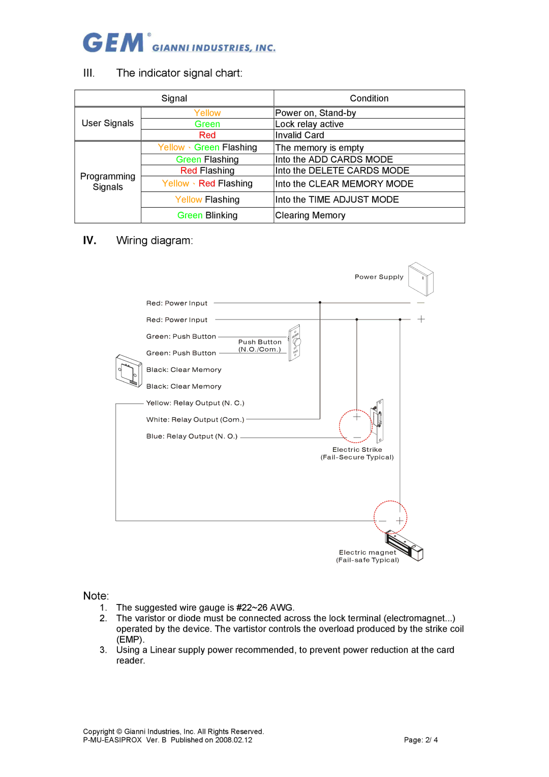
IV. Wiring diagram:
Power Supply
Push Button (N.O./Com.)
Electric Strike
Electric magnet
Note:
1.The suggested wire gauge is #22~26 AWG.
2.The varistor or diode must be connected across the lock terminal (electromagnet...) operated by the device. The vartistor controls the overload produced by the strike coil (EMP).
3.Using a Linear supply power recommended, to prevent power reduction at the card reader.
Copyright © Gianni Industries, Inc. All Rights Reserved. |
|
Page: 2/ 4 |