INSTALLATIONINSTRUCTIONS
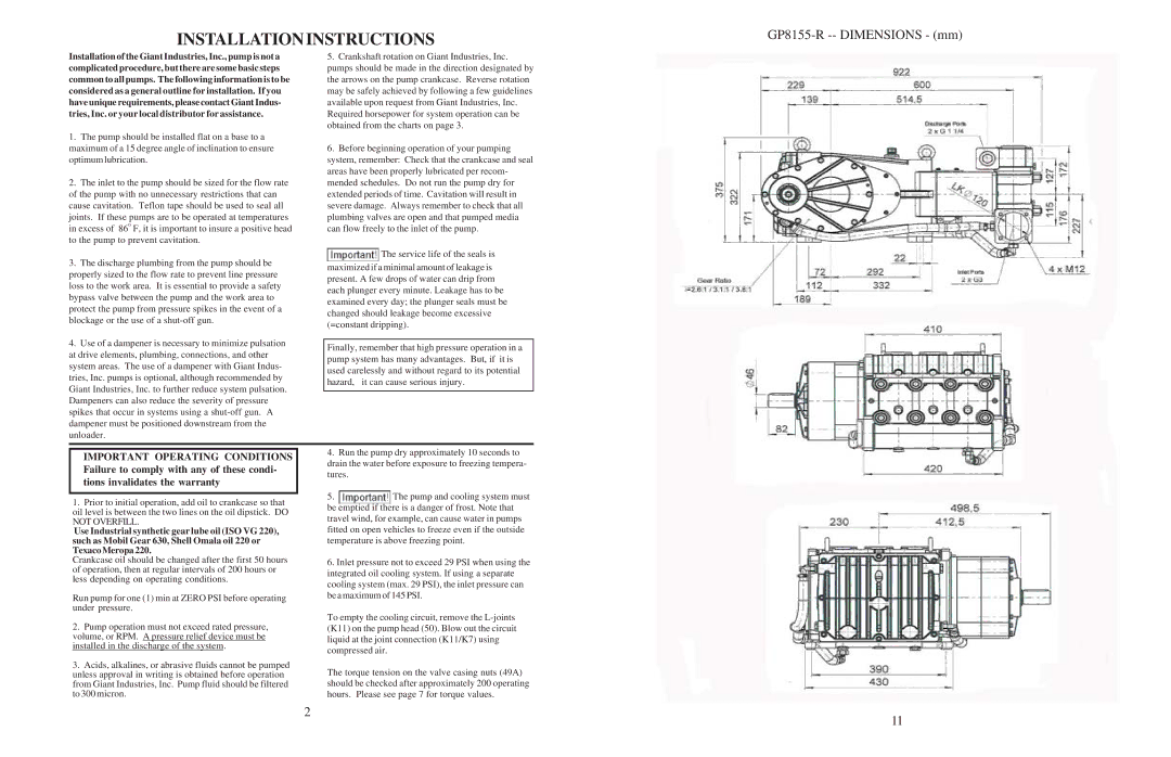
GP8155-R -- DIMENSIONS - (mm)
Installation of the Giant Industries, Inc., pump is not a complicated procedure, but there are some basic steps common to all pumps. The following information is to be considered as a general outline for installation. If you haveuniquerequirements,pleasecontactGiantIndus- tries, Inc. or your local distributor for assistance.
1.The pump should be installed flat on a base to a maximum of a 15 degree angle of inclination to ensure optimum lubrication.
2.The inlet to the pump should be sized for the flow rate of the pump with no unnecessary restrictions that can cause cavitation. Teflon tape should be used to seal all
joints. If these pumps are to be operated at temperatures in excess of 86o F, it is important to insure a positive head to the pump to prevent cavitation.
3.The discharge plumbing from the pump should be properly sized to the flow rate to prevent line pressure loss to the work area. It is essential to provide a safety bypass valve between the pump and the work area to protect the pump from pressure spikes in the event of a blockage or the use of a
4.Use of a dampener is necessary to minimize pulsation at drive elements, plumbing, connections, and other system areas. The use of a dampener with Giant Indus- tries, Inc. pumps is optional, although recommended by Giant Industries, Inc. to further reduce system pulsation. Dampeners can also reduce the severity of pressure spikes that occur in systems using a
5.Crankshaft rotation on Giant Industries, Inc. pumps should be made in the direction designated by the arrows on the pump crankcase. Reverse rotation may be safely achieved by following a few guidelines available upon request from Giant Industries, Inc. Required horsepower for system operation can be obtained from the charts on page 3.
6.Before beginning operation of your pumping system, remember: Check that the crankcase and seal areas have been properly lubricated per recom- mended schedules. Do not run the pump dry for extended periods of time. Cavitation will result in severe damage. Always remember to check that all plumbing valves are open and that pumped media can flow freely to the inlet of the pump.
![]() The service life of the seals is
The service life of the seals is
maximized if a minimal amount of leakage is present. A few drops of water can drip from each plunger every minute. Leakage has to be examined every day; the plunger seals must be changed should leakage become excessive (=constant dripping).
Finally, remember that high pressure operation in a pump system has many advantages. But, if it is used carelessly and without regard to its potential hazard, it can cause serious injury.
IMPORTANT OPERATING CONDITIONS Failure to comply with any of these condi- tions invalidates the warranty
1.Prior to initial operation, add oil to crankcase so that oil level is between the two lines on the oil dipstick. DO NOT OVERFILL.
Use Industrial synthetic gear lube oil (ISO VG 220), such as Mobil Gear 630, Shell Omala oil 220 or TexacoMeropa220.
Crankcase oil should be changed after the first 50 hours of operation, then at regular intervals of 200 hours or less depending on operating conditions.
Run pump for one (1) min at ZERO PSI before operating under pressure.
2.Pump operation must not exceed rated pressure, volume, or RPM. A pressure relief device must be installed in the discharge of the system.
3.Acids, alkalines, or abrasive fluids cannot be pumped unless approval in writing is obtained before operation from Giant Industries, Inc. Pump fluid should be filtered to 300 micron.
4.Run the pump dry approximately 10 seconds to drain the water before exposure to freezing tempera- tures.
5.The pump and cooling system must
be emptied if there is a danger of frost. Note that travel wind, for example, can cause water in pumps fitted on open vehicles to freeze even if the outside temperature is above freezing point.
6.Inlet pressure not to exceed 29 PSI when using the integrated oil cooling system. If using a separate cooling system (max. 29 PSI), the inlet pressure can be a maximum of 145 PSI.
To empty the cooling circuit, remove the
The torque tension on the valve casing nuts (49A) should be checked after approximately 200 operating hours. Please see page 7 for torque values.
2 | 11 |
|