REPAIR INSTRUCTION - P200A-3100/5100 SERIES
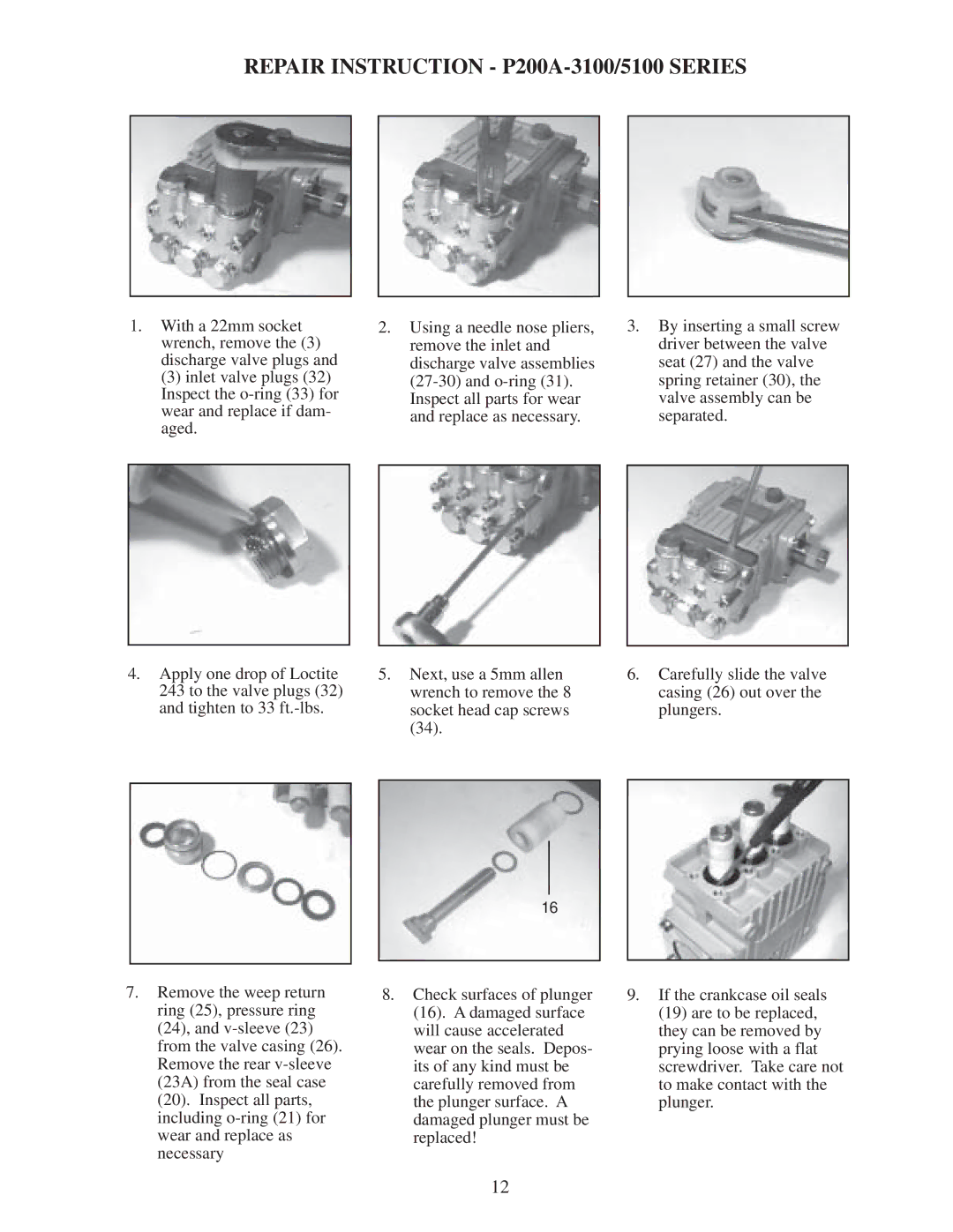
1.With a 22mm socket wrench, remove the (3) discharge valve plugs and
(3) inlet valve plugs (32) Inspect the
4.Apply one drop of Loctite 243 to the valve plugs (32) and tighten to 33
2.Using a needle nose pliers, remove the inlet and discharge valve assemblies
5.Next, use a 5mm allen wrench to remove the 8 socket head cap screws (34).
3.By inserting a small screw driver between the valve seat (27) and the valve spring retainer (30), the valve assembly can be separated.
6.Carefully slide the valve casing (26) out over the plungers.
7.Remove the weep return ring (25), pressure ring (24), and
16
8.Check surfaces of plunger (16). A damaged surface will cause accelerated wear on the seals. Depos- its of any kind must be carefully removed from the plunger surface. A damaged plunger must be replaced!
9.If the crankcase oil seals (19) are to be replaced, they can be removed by prying loose with a flat screwdriver. Take care not to make contact with the plunger.
12