AMD Socket 939 Processor Motherboard
GA-K8N51PVMT-9-RH
Users Manual
GA-K8N51PVMT-9-RH
Motherboard
GA-K8N51PVMT-9-RH Mar. 1
Motherboard
Product Manual Classification
Copyright
Table of Contents
Chapter 4 Appendix
Chapter 3 Drivers Installation
GA-K8N51PVMT-9-RH
GA-K8N51PVMT-9-RH Motherboard Layout
Block Diagram
Page
Instances of Non-Warranty
Chapter 1Hardware Installation
1-1 Considerations Prior to Installation
Installation Notices
Internal Connectors
Feature Summary
2 IDE connectors IDE1, IDE2 with UDMA 33/ATA 66/ATA 100/ATA
4 SATA 3Gb/s connectors SATAII01, SATAII23, allowing connection
Rear Panel I/O
English
English
1-3 Installation of the CPU and CPU Cooler
1-3-1 Installation of the CPU
English
1-3-2 Installation of the CPU Cooler
Notch DDR
1-4 Installation of Memory
English
English
Dual Channel Memory Configuration
English
1-5 Installation of Expansion Cards
TV Out Port Note
PS/2 Keyboard and PS/2 Mouse Connector
1-6 I/O Back Panel Introduction
Parallel Port
HDTV NTSC/PAL TV Projector
English
HDTV Component
Pb/AV Pr TV Out Port Y S-Video Output Video Adapter
English
1-7 Connectors Introduction
PSONsoft On/Off
1/2 ATX12V / ATX Power Connector
English
Pin No
English
3/4 CPUFAN / SYSFAN Cooler Fan Power Connector
5 FDD FDD Connector
English
6 IDE1 / IDE2 IDE Connector
7 SATAII0/1/2/3 SATA 3Gb/s Connectors, Controlled by nForce
English
9 BATTERY
8 PWRLED
MSG+ MSG- PW+ PW
10 FPANEL Front Panel Jumper
MSG Message LED/Power/Sleep LED
English
English
11 FAUDIO Front Audio Panel Connector
12 CDIN CD In Connector
Connect CD-ROM or DVD-ROM audio out to the connector
English
13 F USB1 / FUSB2 Front USB Connector
14 F11394 IEEE 1394 Connector
English
16 COMA COMA Connector
15 SPDIFIO SPDIF In/Out
Open Normal
17 CLRCMOS Clear CMOS
18 CI Chassis Intrusion, Case Open
English
Main Menu
Chapter 2 BIOS Setup
Status Page Setup Menu / Option Page Setup Menu
CONTROL KEYS
English
The Main Menu For example BIOS Ver. F3a
F12 For Boot Menu
F12 For Boot Menu
„ PnP/PCI Configuration
„ Standard CMOS Features
„ Advanced BIOS Features
„ Power Management Setup
IDE Channel 0 Master/Slave IDE Channel 1 Master/Slave
Standard CMOS Features
Date
Time
Base Memory
Floppy 3 Mode Support for Japan Area
Drive A
Memory
Boot Up Floppy Seek
Advanced BIOS Features
Hard Disk Boot Priority
First / Second / Third Boot Device
Onboard GPU
Password Check
Init Display First
Frame Buffer Size
Enabled
SATAII RAID Config
Integrated Peripherals
SATA-II RAID function
SATA-II 2 Secondary RAID
Enabled
Enable SATAII 2 1st SATA RAID function
SATA-II 2 Primary RAID
Onboard LAN Function
Onboard LAN Boot ROM
Parallel Port Mode
Onboard Audio Function
PME Event Wake Up
Power Management Setup
Power-On by Alarm
ACPI Suspend Type
AC BACK Function
Power On By Keyboard
KB Power ON Password
Power On By Mouse
Auto assign IRQ to PCI 1. Default value
PnP/PCI Configurations
PCI 1 IRQ Assignment
PCI 2 IRQ Assignment
Case Opened
Current VoltageV VCORE / DDR Power / +3.3V / +12V
System/CPU Temperature
PC Health Status
English
CPU Smart FAN Control Note
PCIE Clock
TV Mode Support
Frequency/Voltage Control
CPU Frequency
English
Load Fail-Safe Defaults
Load Optimized Defaults
English
Set Supervisor/User Password
2-10
Type N will return to Setup Utility
2-11 Save & Exit Setup
2-12 Exit Without Saving
Type Y will quit the Setup Utility without saving to RTC CMOS
GA-K8N51PVMT-9-RH Motherboard
English
English
Chapter 3Drivers Installation
3-1 Install Chipset Drivers
English
3-2 Software Application
3-3 Software Information
English
3-4 Hardware Information
3-5 Contact Us
Drivers Installation
English
3-6 Connecting the Video Output Devices
4-1-1 EasyTune 5 Introduction
Chapter
Appendix
4-1 Unique Software Utilities
English
4-1-2 Xpress Recovery2 Introduction
How to use the Xpress Recovery2
System requirements
Precautions
1. RESTORE
2. BACKUP
4. REBOOT
Before You Begin
4-1-3 Flash BIOS Method Introduction
Updating BIOS with Q-FlashTM Utility on Dual BIOS Motherboards
Method 1 Q-FlashTM Utility
Task menu for Q-Flash utility
Exploring the Q-FlashTM / Dual BIOS utility screen
Task menu for Dual BIOS utility
Entering the Q-FlashTM utility
English
Using the Q-FlashTM utility
Steps
The BIOS file becomes Fab after updating
3. Press Y button on your keyboard after you are sure to update BIOS
Please do not take out the floppy disk when it begins flashing BIOS
You can repeat Step 1 to 4 to flash the backup BIOS, too
Press Y on your keyboard to save and exit
Updating BIOS with Q-FlashTM Utility on Single-BIOS Motherboards
Part Two
English
Action bar
Exploring the Q-FlashTM utility screen
Using the Q-FlashTM utility
Task menu for Q-Flash utility
English
Congratulation!! You have updated BIOS successfully
Copy BIOS completed - Pass
Are you sure to RESET ?
English
Method 2 @BIOSTM Utility
1. Methods and steps
English
2. Note
2 Configuring SATA controller mode and boot sequence in BIOS Setup
4-1-4 Configuring SATA Hard Drives
To configure SATA hard drives, follow the steps below
1 Installing SATA hard drives in your computer
English
English
If you do not create RAID, select Hard Disk Boot Priority under the Advanced BIOS Features menu. In the Hard Disk Boot Priority submenu, select the model of the SATA hard drive onto which you wish to install Microsoft Windows 2000/XP. You should see a screen similar to Figure 3 below
GA-K8N51PVMT-9-RH Motherboard
Step Save and exit BIOS Setup
English
Step
English
3 Configuring RAID set in RAID BIOS
MediaShield IDE ROM BIOS Copyright C 2005 NVIDIA Corp Detecting array
Press F10 to enter RAID setup utility
English
Next, select the hard drives which you wish to be included in the disk array. The Free Disks section displays the information about the currently installed SATA hard drives. Press the TAB key to move to the Free Disks section. Select the target hard drives using the UP or DOWN ARROW key and use the RIGHT ARROW key to add the hard drives to the Array Disks section Figure
R Rebuild
English
N New Array ENTER Detail
English
4 Making a SATA Driver Disk
cd bootdrv menu
S=Specify Additional Device ENTER=Continue F3=Exit
5 Installing SATA controller driver during OS installation
Press F6 if you need to install a third party SCSI or RAID driver
English
English
If Setup correctly recognizes the driver in the floppy disk, a controller menu similar to Figure 17 below will appear. Use the ARROW keys to select NVIDIA RAID CLASS DRIVER* Figure 17 and press ENTER. Later, when a screen similar to Figure 18 appears, you must press S to select additional driver. The screen will return to previous screen as shown in Figure 17. Select NVIDIA nForce Storage Controller and press ENTER
English
Disabled
6 Configuring a bootable RAID array with Microsoft Windows
Disabled
Disabled
English
English
English
Stereo Speakers Connection and Settings
4-1-5 2- / 4- / 6- / 8- Channel Audio Function Introduction
English
4 Channel Audio Setup
English
6 Channel Audio Setup
English
8 Channel Audio Setup
English
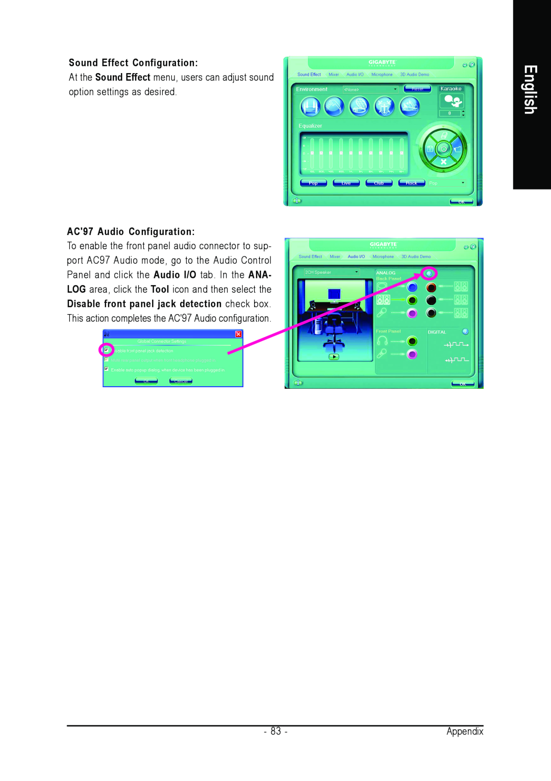
Sound Effect Configuration
AC97 Audio Configuration
English
4-2 Troubleshooting
Appendix
English
GA-K8N51PVMT-9-RH Motherboard
English
English
Contact Us
English
y GIGABYTE Global Service System