AMD Socket AM2 Processor Motherboard
GA-M55S-S3 rev
Users Manual
GA-M55S-S3 rev Nov. 10
Motherboard
Motherboard
GA-M55S-S3 rev
Product Manual Classification
Copyright
Table of Contents
Chapter 4 Appendix
Chapter 3 Drivers Installation
4-1-1
4-1-2
Optional Accessories
Item Checklist
GA-M55S-S3
GA-M55S-S3 rev. 2.0 Motherboard Layout
nForce
Block Diagram
PCI-ECLK 100 MHz PCI Express PCI Express Bus
1-1 Considerations Prior to Installation
Chapter 1Hardware Installation
Installation Notices
Instances of Non-Warranty
English
1-2 Feature Summary
4 SATA 3Gb/s connectors SATAII1, SATAII2, SATAII3, SATAII4, allow
Speaker Out / Center/Subwoofer Speaker Out / Side Speaker Out
English
English
1-3 Installation of the CPU and CPU Cooler
1-3-1 Installation of the CPU
English
1-3-2 Installation of the CPU Cooler
Fig.1
Fig.2
Notch DDRII
1-4 Installation of Memory
English
English
Dual Channel Memory Configuration
English
1-5 Installation of Expansion Cards
1-6 I/O Back Panel Introduction
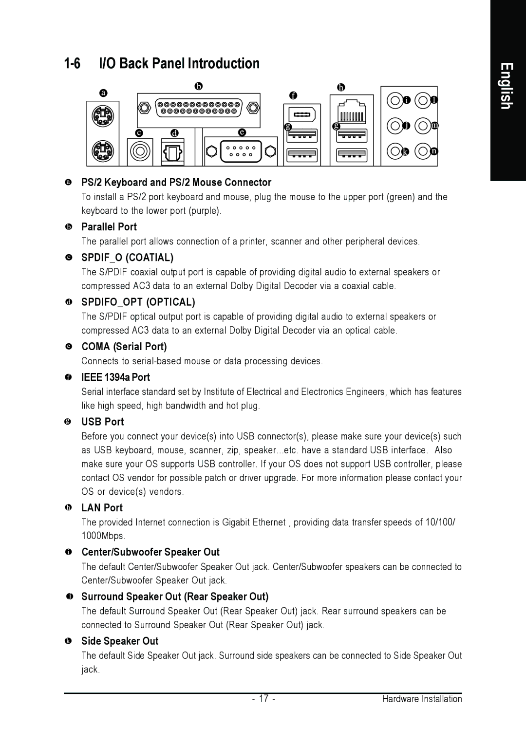
PS/2 Keyboard and PS/2 Mouse Connector
Parallel Port
SPDIFO COATIAL
Line In
Connectors Introduction
Line Out Front Speaker Out
MIC In
English
1/2 ATX12V / ATX Power Connector
+5V Only for 24-pin ATX
3.3VOnly for 24-pin ATX
4/5/6 CPUFAN / SYSFAN / PWRFAN Cooler Fan Power Connector
3 PCIE12V Power Connector
English
CPUFAN
English
7 FDD FDD Connector
8 IDE1 IDE Connector
English
9 SATAII1 / 2 / 3 / 4 SATA 3Gb/s Connectors, Controlled by nForce
10 BATTERY
Speaker Connector
11 FPANEL Front Panel Jumper
Switch
English
English
13 FAUDIO Front Audio Connector
12 PWRLED
15 SPDIFI S/PDIF In Connector
14 CDIN CD In Connector
Connect CD-ROM or DVD-ROM audio out to the connector
English
English
16 F USB1 / FUSB2 / FUSB3 Front USB Connector
17 F11394 / F21394 Front IEEE 1394 Connector
English
18 CI Chassis Intrusion, Case Open
19 CLRCMOS Clear CMOS
GA-M55S-S3 rev. 2.0 Motherboard
English
Status Page Setup Menu / Option Page Setup Menu
Chapter 2 BIOS Setup
CONTROL KEYS
Main Menu
F12 For Boot Menu
The Main Menu For example BIOS Ver. FAa
BIOS Setting Recovery
English
Advanced BIOS Features
Standard CMOS Features
Power Management Setup
PnP/PCI Configuration
Date
Standard CMOS Features
Time
IDE Channel 0 Master/Slave
Floppy 3 Mode Support for Japan Area
Drive A / Drive B
Halt on
Memory
Hard Disk Boot Priority
Advanced BIOS Features
First / Second / Third Boot Device
Boot Up Floppy Seek
Away Mode
Password Check
Init Display First
English
Integrated Peripherals
Serial-ATA RAID Config
NV SATA RAID function
NV SATA 1 Secondary RAID
On-Chip IDE Channel0
NV SATA 2 Secondary RAID
On-Chip MAC Lan
NV Serial-ATA Controller
Onboard
Onboard LAN Boot ROM
Onboard Serial Port
Onboard Parallel Port
On-Chip USB
ECP Mode Use DMA
USB Keyboard Support
USB Mouse Support
ACPI Suspend Type
Power-On by Alarm
PME Event Wake Up
Modem Ring On
Power On By Keyboard
Power On By Mouse
KB Power ON Password
AC BACK Function
PCI 2 IRQ Assignment
2-5 PnP/PCI Configurations
PCI 1 IRQ Assignment
English
Current CPU/POWER/SYSTEM FAN Speed RPM
Current CPU Temperature
CPU Warning Temperature
CPU/POWER/SYSTEM FAN Fail Warning
CPU Smart FAN Mode
CPU Smart FAN Control Note
Set to Voltage when you use a CPU fan with a 3-pin fan power cable
English
CPU Frequency MHz
MB Intelligent TweakerM.I.T
PCIE Clock MHz
CPU Clock Ratio
CPU Voltage Control
CPU HT-Link Voltage
Normal CPU Vcore
English
Load Optimized Defaults
Load Fail-Safe Defaults
Load Fail-Safe DefaultsSaveY/N?& ExitN Setup
Load Optimized DefaultsSaveY/N?& ExitN Setup
English
2-10 Set Supervisor/User Password
2-12 Exit Without Saving
2-11 Save & Exit Setup
Type Y will quit the Setup Utility without saving to RTC CMOS
Type N will return to Setup Utility
GA-M55S-S3 rev. 2.0 Motherboard
English
English
Chapter 3Drivers Installation
3-1 Install Chipset Drivers
English
3-2 Software Applications
3-3 Driver CD Information
3-5 Contact Us
3-4 Hardware Information
English
This page lists all device you have for this motherboard
GA-M55S-S3 rev. 2.0 Motherboard
English
4-1 Unique Software Utilities
Chapter 4 Appendix
4-1-1 EasyTune 5 Introduction
User Interface Overview
How to use the Xpress Recovery2
4-1-2 Xpress Recovery2 Introduction
Boot from CD/DVD F9 Xpress Recovery2
System requirements
1. RESTORE
The Main Screen of Xpress Recovery2
2. BACKUP
4. REBOOT
Updating BIOS with Q-FlashTM Utility on Dual BIOS Motherboards
4-1-3 Flash BIOS Method Introduction
Method 1 Q-FlashTM Utility
Before You Begin
Task menu for Dual BIOS utility
Exploring the Q-FlashTM / Dual BIOS utility screen
Entering the Q-FlashTM utility
Task menu for Q-Flash utility
Steps
Using the Q-FlashTM utility
English
disk
Please do not take out the floppy disk when it begins flashing BIOS
3. Press Y button on your keyboard after you are sure to update BIOS
BIOS, too
The BIOS file becomes Fba after updating
Part Two
Updating BIOS with Q-FlashTM Utility on Single-BIOS Motherboards
English
Save to CMOS and EXIT Y/N?Set SupervisorY
Using the Q-FlashTM utility
Exploring the Q-FlashTM utility screen
Task menu for Q-Flash utility
Action bar
Copy BIOS completed - Pass
Congratulation!! You have updated BIOS successfully
Are you sure to RESET ?
English
English
Method 2 @BIOSTM Utility
1. Methods and steps
English
2. Note
To configure SATA hard drives, follow the steps below
4-1-4 Configuring SATA Hard Drives
1 Installing SATA hard drives in your computer
Before you begin
English
2 Configuring SATA controller mode and boot sequence in BIOS Setup
Step
Step Save and exit BIOS Setup
English
MediaShield ROM BIOS Copyright C 2006 NVIDIA Corp Detecting array
3 Configuring RAID set in RAID BIOS
Press F10 to enter RAID setup utility
English
English
Next, select the hard drives which you wish to be included in the disk array. The Free Disks section displays the information about the currently installed SATA hard drives. Press the TAB key to move to the Free Disks section. Select the target hard drives using the UP or DOWN ARROW key and use the RIGHT ARROW key to add the hard drives to the Array Disks section Figure
English
B Set Boot
N New Array ENTER Detail
R Rebuild
cd bootdrv menu
4 Making a SATA Driver Disk
English
Figure 10Figure Note For users without a startup disk
Press F6 if you need to install a third party SCSI or RAID driver
5 Installing SATA controller driver during OS installation
English
S=Specify Additional Device ENTER=Continue F3=Exit
English
If Setup correctly recognizes the driver in the floppy disk, a controller menu similar to Figure 15 below will appear. Use the ARROW keys to select NVIDIA RAID CLASS DRIVER Figure 15 and press ENTER. Later, when a screen similar to Figure 16 appears, you must press S to select additional driver. The screen will return to previous screen as shown in Figure 15. Select NVIDIA nForce Storage Controller and press ENTER
English
English
Stereo Speakers Connection and Settings
4-1-5 2- / 4- / 6- / 8- Channel Audio Function Introduction
English
4 Channel Audio Setup
English
6 Channel Audio Setup
English
8 Channel Audio Setup
English
Sound Effect Configuration
AC97 Audio Configuration
English
4-2 Troubleshooting
Appendix
English
GA-M55S-S3 rev. 2.0 Motherboard
English
Appendix
English
English
Contact Us
Then select your language to enter the system
y GIGABYTE Global Service System
English