English
1-4 Installation of Memory
Before installing the memory modules, please comply with the following conditions:
1. Please make sure that the memory used is supported by the motherboard. It is recommended that memory of similar capacity, specifications and brand be used.
2.Before installing or removing memory modules, please make sure that the computer power is switched off to prevent hardware damage.
3.Memory modules have a foolproof insertion design. A memory module can be installed in only one direction. If you are unable to insert the module, please switch the direction.
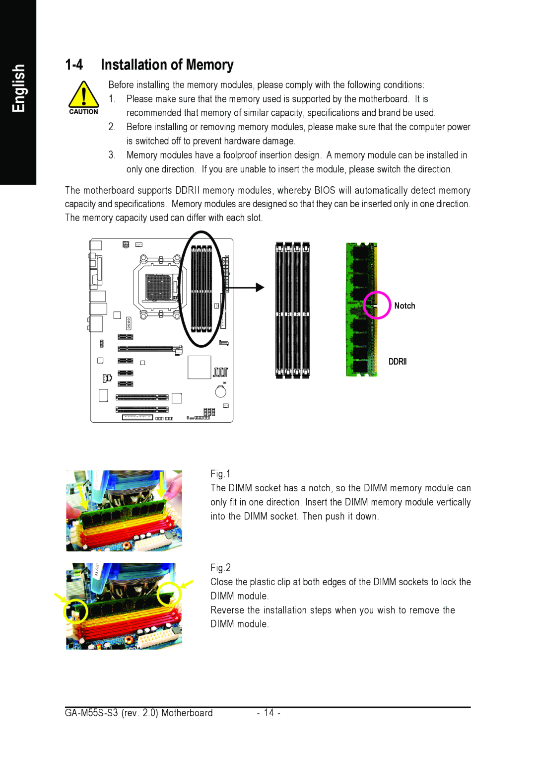
The motherboard supports DDRII memory modules, whereby BIOS will automatically detect memory capacity and specifications. Memory modules are designed so that they can be inserted only in one direction. The memory capacity used can differ with each slot.
Notch
DDRII
Fig.1
The DIMM socket has a notch, so the DIMM memory module can only fit in one direction. Insert the DIMM memory module vertically into the DIMM socket. Then push it down.
Fig.2
Close the plastic clip at both edges of the DIMM sockets to lock the DIMM module.
Reverse the installation steps when you wish to remove the DIMM module.
- 14 - |