Water supply

u The total opening of the cabinet (i.e. 70-3/8 in. (1788 mm)) plus the thickness of the top as well as the floor board (usually 3/4 in. (19 mm)) minus the height of the freezer door panel (xxx in. (xxx mm)) as calculated above and subtract the width of the gap (approximately 1/8 in. (3 mm)): 70-3/8 in. + 3/4 in. + 3/4 in. - xxx in. - 1/8 in. = 71-25/32 in. - xxx in. ( 1788 mm + 19 mm + 19 mm - xxx mm - 3 mm = 1823 mm – xxx mm )

5 Water supply*

WARNING

Electrical Shock Hazard!

u Do not make the water connection while the appliance is connected to an electrical outlet.

u Disconnect the water supply before connecting the water lines for the IceMaker.

u The connection to the water supply may only be made by a trained and licensed plumber.

WARNING

Poisoning Hazard!

u The water quality must comply with the drinking water regulations for the geographical area where the appliance is located.

u The IceMaker is designed exclusively to make ice cubes in quantities needed by a household and must only be operated with water appropriate for this purpose.

-The water pressure must be between 21.76 psi (1.5 bar) and 87.02 psi (6 bar). (0,15 MPa - 0,6 MPa)

-Water must be supplied to the appliance by means of a cold- water pipe that can withstand the operating pressure and

conforms to hygiene regulations.

Use the supplied steel hose (59-1/16 '' (1.5 m), metric thread) to connect to the water supply. A 118-1/8 '' (3 m) hose is available from Customer Service. This hose must be installed by a qualified fitter.

The connecting piece of the hose contains a filter with a gasket seal.

-A shut-off valve must be provided between the hose line and the domestic water supply to turn off the water supply, if necessary.

-All devices and fixtures used to supply water must comply with the regulations in force in the respective country.

- Do not damage or bend the water supply pipe during installation.

u Connect the straight portion of the supplied stainless steel hose to the solenoid valve.

The solenoid valve is located on the back of the appliance at the bottom. It has a Metric R¾ male connection.

u Connect the bent portion of the stainless steel hose to the shut-off valve.

u Open the shut-off valve of the water supply pipe and check the entire water system to ensure there are no leaks.

Before initial operation:

u Have a competent fitter bleed the water supply pipe.

6 Installation

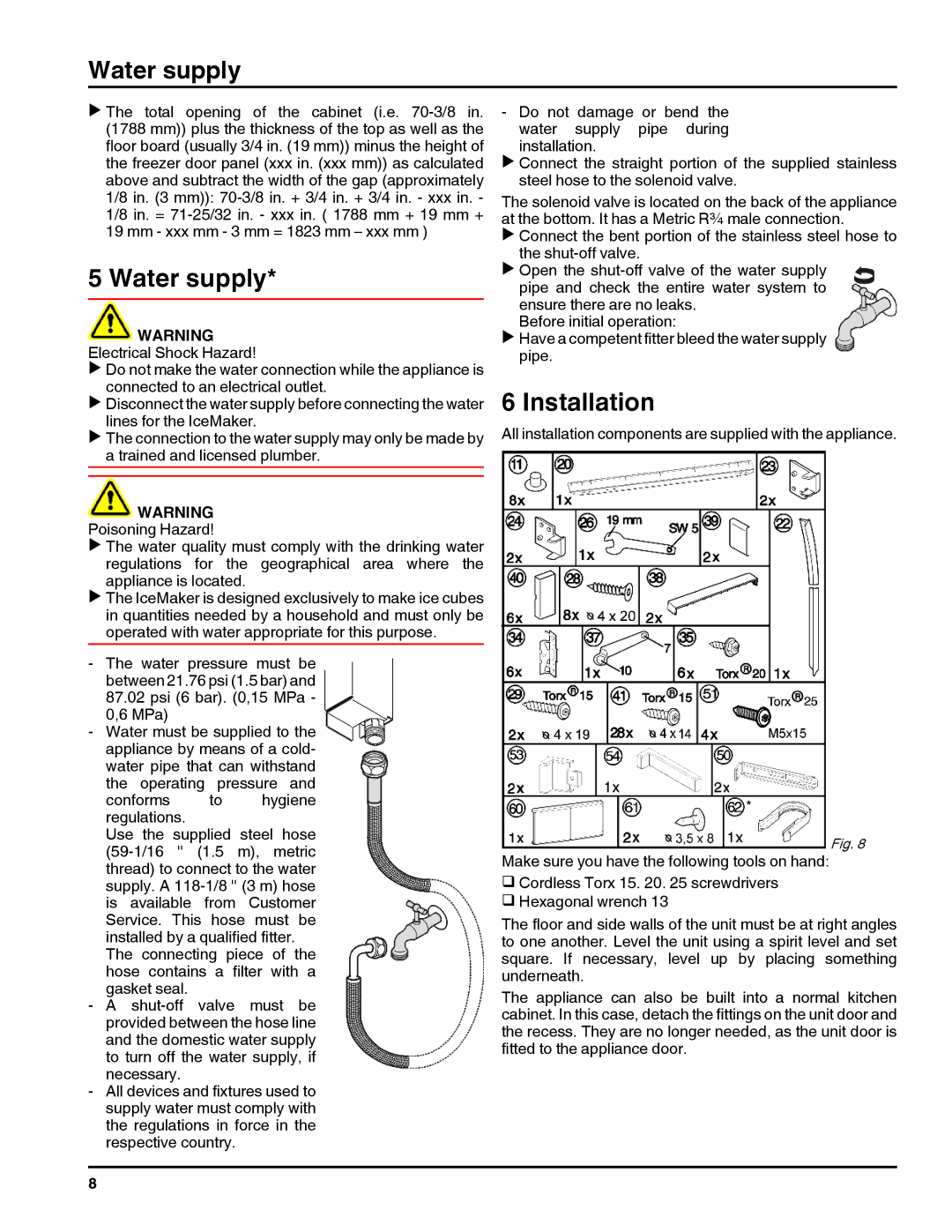
All installation components are supplied with the appliance.

Make sure you have the following tools on hand:Fig. 8 q Cordless Torx 15. 20. 25 screwdrivers

q Hexagonal wrench 13

The floor and side walls of the unit must be at right angles to one another. Level the unit using a spirit level and set square. If necessary, level up by placing something underneath.

The appliance can also be built into a normal kitchen cabinet. In this case, detach the fittings on the unit door and the recess. They are no longer needed, as the unit door is fitted to the appliance door.

8

Page 8
Image 8
Liebherr HC 1011/1060, HC 1001/1050, 7084000-01, 20707 installation instructions Water supply, Installation

20707, 7084000-01, HC 1001/1050, HC 1011/1060 specifications

The Liebherr HC 1011 and HC 1060, along with the HC 1001 and HC 1050, represent a significant advancement in hydraulic crane technology. These models are designed for optimal performance, versatility, and efficiency in various lifting applications, making them indispensable in construction and industrial settings.

One of the key features of the Liebherr HC series is their exceptional lifting capabilities. The HC 1011 and HC 1060 are designed with robust hydraulic systems that provide impressive load capacities. These cranes can lift heavy materials with precision, allowing for efficient operation on job sites that require the moving of substantial loads. The HC 1001 and HC 1050 offer similar advantages, ensuring that projects can be completed smoothly and without unnecessary delays.

Technological innovation is a hallmark of Liebherr products, and these cranes are no exception. They feature advanced control systems that facilitate easy operation, enabling both experienced operators and those new to crane operation to work effectively. These systems also include safety features that prevent overloads and ensure stable lifting, reducing the risk of accidents on the job site.

The ergonomic design of the operator’s cabin in the HC series enhances comfort and visibility, enabling operators to maintain focus during operation. The cabin is equipped with user-friendly controls and displays, ensuring that vital crane functions are easily accessible. This design consideration is critical for maximizing productivity while minimizing operator fatigue.

Another significant characteristic of the Liebherr HC series is their durability and maintenance efficiency. Constructed with high-quality materials, these cranes are built to withstand the rigors of demanding work environments. Moreover, Liebherr has designed the cranes with accessibility in mind, making routine maintenance straightforward and quick, which minimizes downtime.

With features such as a modular design, these cranes can be customized to meet specific operational needs. Liebherr provides a range of attachments and accessories that enhance the versatility of the HC 1011, HC 1060, HC 1001, and HC 1050, allowing them to perform a variety of tasks beyond standard lifting operations.

In summary, the Liebherr HC 1011/1060 and HC 1001/1050 cranes combine power, technology, and durability to deliver a top-tier lifting solution. Their sophisticated features, safety mechanisms, and ergonomic design make them ideal for modern construction and industrial projects, ensuring that users can rely on them for both efficiency and safety in their lifting tasks.