 Fig. 22
 Fig. 24
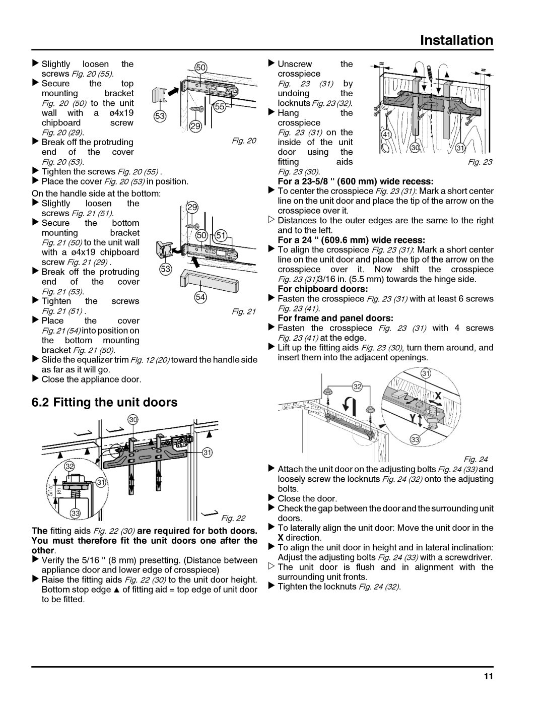
20707, 7084000-01, HC 1001/1050, HC 1011/1060 specifications
The Liebherr HC 1011 and HC 1060, along with the HC 1001 and HC 1050, represent a significant advancement in hydraulic crane technology. These models are designed for optimal performance, versatility, and efficiency in various lifting applications, making them indispensable in construction and industrial settings.One of the key features of the Liebherr HC series is their exceptional lifting capabilities. The HC 1011 and HC 1060 are designed with robust hydraulic systems that provide impressive load capacities. These cranes can lift heavy materials with precision, allowing for efficient operation on job sites that require the moving of substantial loads. The HC 1001 and HC 1050 offer similar advantages, ensuring that projects can be completed smoothly and without unnecessary delays.
Technological innovation is a hallmark of Liebherr products, and these cranes are no exception. They feature advanced control systems that facilitate easy operation, enabling both experienced operators and those new to crane operation to work effectively. These systems also include safety features that prevent overloads and ensure stable lifting, reducing the risk of accidents on the job site.
The ergonomic design of the operator’s cabin in the HC series enhances comfort and visibility, enabling operators to maintain focus during operation. The cabin is equipped with user-friendly controls and displays, ensuring that vital crane functions are easily accessible. This design consideration is critical for maximizing productivity while minimizing operator fatigue.
Another significant characteristic of the Liebherr HC series is their durability and maintenance efficiency. Constructed with high-quality materials, these cranes are built to withstand the rigors of demanding work environments. Moreover, Liebherr has designed the cranes with accessibility in mind, making routine maintenance straightforward and quick, which minimizes downtime.
With features such as a modular design, these cranes can be customized to meet specific operational needs. Liebherr provides a range of attachments and accessories that enhance the versatility of the HC 1011, HC 1060, HC 1001, and HC 1050, allowing them to perform a variety of tasks beyond standard lifting operations.
In summary, the Liebherr HC 1011/1060 and HC 1001/1050 cranes combine power, technology, and durability to deliver a top-tier lifting solution. Their sophisticated features, safety mechanisms, and ergonomic design make them ideal for modern construction and industrial projects, ensuring that users can rely on them for both efficiency and safety in their lifting tasks.