Assembly
It is necessary to fit the safety guard (3), join the handles (5a & 5b) and fit the secondary handle (4).
Joining the handles
1.Insert the lower section of the handle (5b) into the upper section (5a) lining up the hole in the upper handle with the pin in the lower handle.
1 | 2 |
2.Tighten the shaft locking knob to secure it in place.
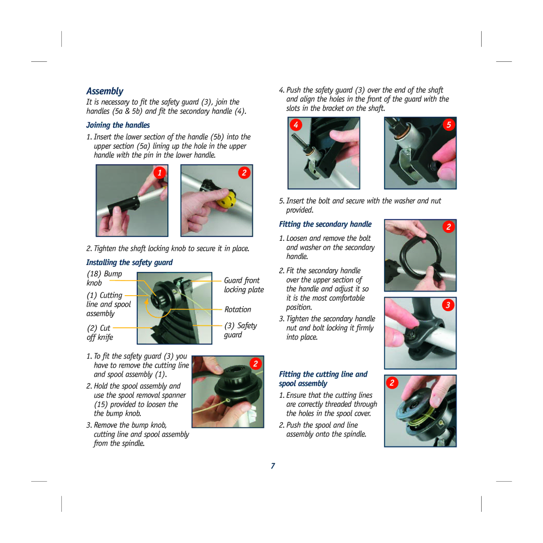
Installing the safety guard
(18) | Bump |
| Guard front | |
| ||||
knob |
|
| ||
|
| locking plate | ||
(1) Cutting |
| |||
|
| |||
line and spool |
| Rotation | ||
assembly |
| |||
|
| |||
(2) Cut |
| (3) Safety | ||
| guard | |||
off knife |
| |||
|
| |||
|
|
| ||
1. To fit the safety guard (3) you | 2 | |||
have to remove the cutting line | ||||
| ||||
and spool assembly (1).
2. Hold the spool assembly and use the spool removal spanner (15) provided to loosen the the bump knob.
3. Remove the bump knob, cutting line and spool assembly from the spindle.
4.Push the safety guard (3) over the end of the shaft and align the holes in the front of the guard with the slots in the bracket on the shaft.
4 |
| 5 |
|
|
|
5.Insert the bolt and secure with the washer and nut provided.
Fitting the secondary handle | 2 | |
1. Loosen and remove the bolt |
| |
and washer on the secondary |
| |
handle. |
| |
2. Fit the secondary handle |
| |
over the upper section of |
| |
the handle and adjust it so |
| |
it is the most comfortable | 3 | |
position. | ||
| ||
3. Tighten the secondary handle |
| |
nut and bolt locking it firmly |
| |
into place. |
| |
Fitting the cutting line and |
| |
2 | ||
spool assembly | ||
| ||
1. Ensure that the cutting lines |
| |
are correctly threaded through |
| |
the holes in the spool cover. |
| |
2. Push the spool and line |
| |
assembly onto the spindle. |
| |
|
|
7