1 Product Specifications
1.1 Intended use
The
IMPORTANT: Risk of damage! The appliances may only be used to heat up potable water. Damage to the appliance due to corrosion cannot be excluded if the water does not correspond to the specifications of the water ordinance.
Any other use or extended use is considered to be improper. The manufacturer/supplier is not liable for any resulting damage.
Intended use includes the observance of the instructions and the adherence to the servicing requirements.
1.2 Data badge
The data badge has been applied to the top of the solar cylinder by the manufacturer.
1.3 Safety devices
The Flurocyl solar cylinder has been provided with all safety and control devices suitable for operation as part of an unvented domestic hot water supply system.
Temperature and pressure relief valve (95°C, 7 bar) Pressure limiting valve (3.5 bar) with line strainer Expansion relief valve (one port valve, 6.0 bar)
Thermal cut out set to 90°C, connected to the solar pump in order to isolate this heat source in the event of failure of the solar control.
Thermal cut out of the immersion heater
Thermal cut out set to 90°C, connected to the motorised 2 port valve, in order to isolate the primary heat source in the event of failure of the domestic water thermostat.
1.4 Safety regulations
This product has been checked for adherence to the building regulations for unvented hot water cylinder systems. It may not be changed or modified in any way whatsoever.
It should be installed by a qualified specialist, who should observe the applicable regulations of the local authorities, the building regulations, the building regulations for Scotland, the building regulations for Northern Ireland and the directives of the local water supply companies. Only original spare parts may be used for the replacement of parts.
1.5 Contents
Check the contents of the pack, see diagram 2.1.
Make sure the cylinder is stored in an upright position in a dry environment prior to its installation.
1.6 Transport
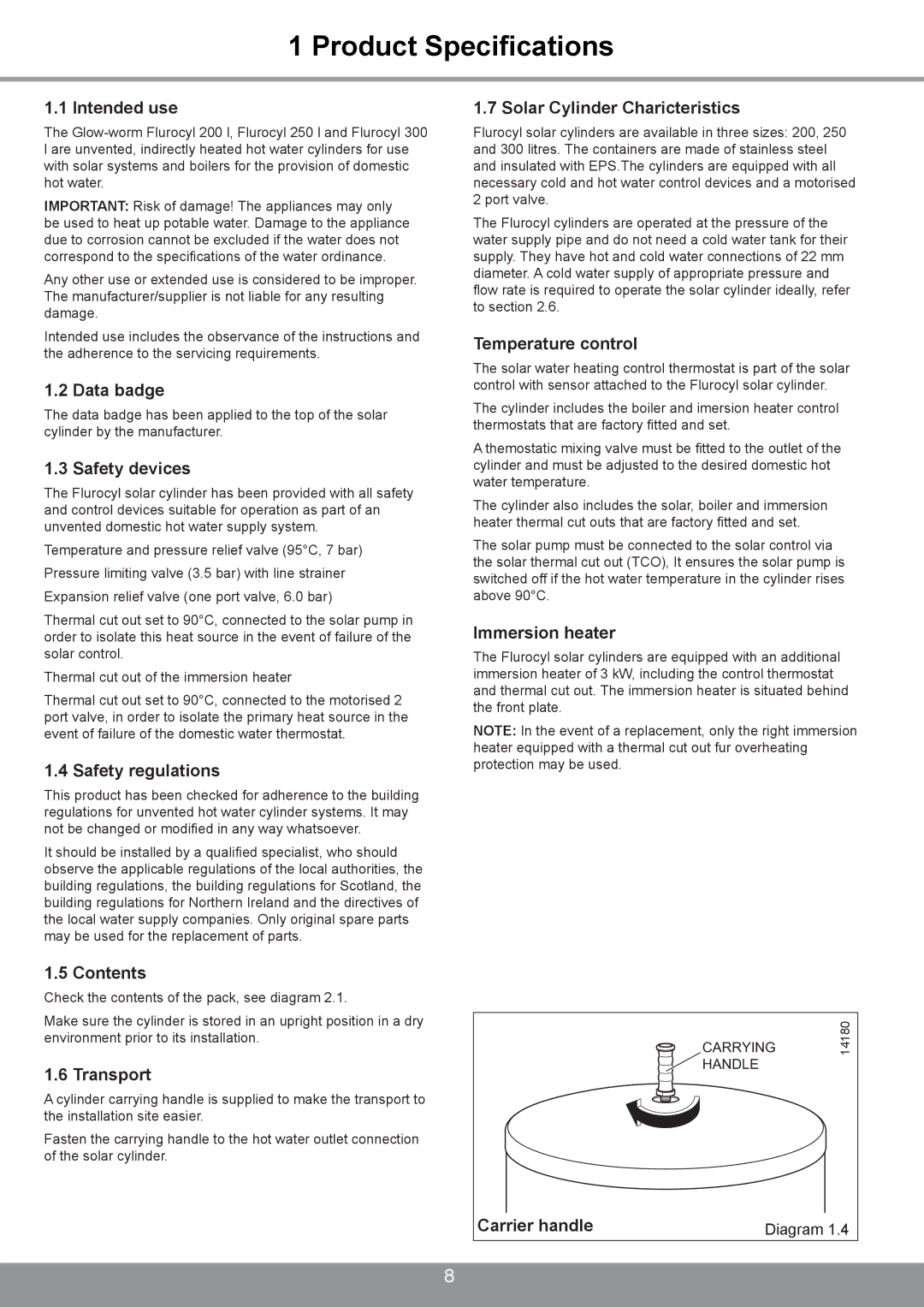
A cylinder carrying handle is supplied to make the transport to the installation site easier.
Fasten the carrying handle to the hot water outlet connection of the solar cylinder.
1.7 Solar Cylinder Charicteristics
Flurocyl solar cylinders are available in three sizes: 200, 250 and 300 litres. The containers are made of stainless steel and insulated with EPS.The cylinders are equipped with all necessary cold and hot water control devices and a motorised 2 port valve.
The Flurocyl cylinders are operated at the pressure of the water supply pipe and do not need a cold water tank for their supply. They have hot and cold water connections of 22 mm diameter. A cold water supply of appropriate pressure and flow rate is required to operate the solar cylinder ideally, refer to section 2.6.
Temperature control
The solar water heating control thermostat is part of the solar control with sensor attached to the Flurocyl solar cylinder.
The cylinder includes the boiler and imersion heater control thermostats that are factory fitted and set.
A themostatic mixing valve must be fitted to the outlet of the cylinder and must be adjusted to the desired domestic hot water temperature.
The cylinder also includes the solar, boiler and immersion heater thermal cut outs that are factory fitted and set.
The solar pump must be connected to the solar control via the solar thermal cut out (TCO), It ensures the solar pump is switched off if the hot water temperature in the cylinder rises above 90°C.
Immersion heater
The Flurocyl solar cylinders are equipped with an additional immersion heater of 3 kW, including the control thermostat and thermal cut out. The immersion heater is situated behind the front plate.
NOTE: In the event of a replacement, only the right immersion heater equipped with a thermal cut out fur overheating protection may be used.
CARRYING | 14180 |
HANDLE |
|
Carrier handle | Diagram 1.4 |
|
|
|
|
