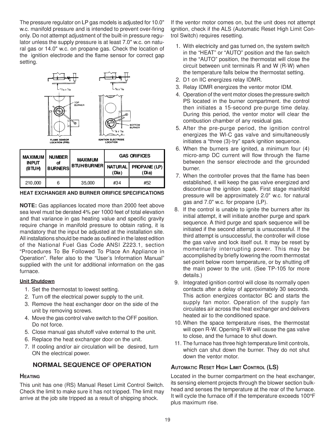
The pressure regulator on LP gas models is adjusted for 10.0" w.c. manifold pressure and is intended to prevent over-firing only. Do not attempt adjustment of the built-in pressure regu- lator unless the supply pressure is at least 7.0" w.c. on natu- ral gas or 14.0" w.c. on propane gas. Check the location of the ignition electrode and the flame sensor for correct gap setting.

MAXIMUM

NUMBER

MAXIMUM

GAS ORIFICES

INPUT

of


BTUH/BURNER

NATURAL

PROPANE (LP)

(BTUH)

BURNERS


(Dia)

(Dia)


210,000

6

35,000

#34

#52


HEAT EXCHANGER AND BURNER ORIFICE SPECIFICATIONS

NOTE: Gas appliances located more than 2000 feet above sea level must be derated 4% per 1000 feet of total elevation and that variance in gas heating value and specific gravity require change in manifold pressure to obtain rating, it is mandatory that the input be adjusted at the installation site. All installations should be made as outlined in the latest edition of the National Fuel Gas Code ANSI Z223.1, section “Procedures To Be Followed To Place An Appliance in Operation”. Refer also to the “User’s Information Manual” supplied with the unit for additional information on the gas furnace.

Unit Shutdown

1.Set the thermostat to lowest setting.

2.Turn off the electrical power supply to the unit.

3.Remove the heat exchanger door on the side of the unit by removing screws.

4.Move the gas control valve switch to the OFF position. Do not force.

5.Close manual gas shutoff valve external to the unit.

6.Replace the heat exchanger door on the unit.

7.If cooling and/or air circulation will be desired, turn ON the electrical power.

NORMAL SEQUENCE OF OPERATION

HEATING

This unit has one (RS) Manual Reset Limit Control Switch. Check the limit to make sure it has not tripped. The limit may arrive at the job site tripped as a result of shipping shock.

If the ventor motor comes on, but the unit does not attempt ignition, check if the ALS (Automatic Reset High Limit Con- trol Switch) requires resetting.

1.With electricity and gas turned on, the system switch in the “HEAT” or “AUTO” position and the fan switch in the “AUTO” position, the thermostat will close the circuit between unit terminals R and W (R-W) when the temperature falls below the thermostat setting.

2.D1 on IIC energizes relay IDMR.

3.Relay IDMR energizes the ventor motor IDM.

4.Operation of the vent motor closes the pressure switch PS located in the burner compartment. the control then initiates a 15-second pre-purge time delay. During this period, the ventor motor will clear the combustion chamber of any residual gas.

5.After the pre-purge period, the ignition control energizes the Wl-C gas valve and simultaneously initiates a “three (3)-try” spark ignition sequence.

6.When the burners are ignited, a minimum four (4) micro-amp DC current will flow through the flame between the sensor electrode and the grounded burner.

7.When the controller proves that the flame has been established, it will keep the gas valve energized and discontinue the ignition spark. First stage manifold pressure will be approximately 2.0" w.c. for natural gas and 7.0" w.c. for propane (LP).

8.If the control is unable to ignite the burners after its initial attempt, it will initiate another purge and spark sequence. A third purge and spark sequence will be initiated if the second attempt is unsuccessful. If the third attempt is unsuccessful, the controller will close the gas valve and lock itself out. It may be reset by momentarily interrupting power. This may be accomplished by briefly lowering the room thermostat set-point below room temperature, or by shutting off the main power to the unit. (See TP-105 for more details.)

9.Integrated ignition control will close its normally open contacts after a delay of approximately 30 seconds. This action energizes contactor BC and starts the supply fan motor. Operation of the supply fan circulates air across the heat exchanger and delivers heated air to the conditioned space.

10.When the space temperature rises, the thermostat will open R-W. Opening R-W will cause the gas valve to close, and the furnace to shut down.

11.The furnace has three high temperature limit controls, which can shut down the burner. They do not shut down the ventor motor.

AUTOMATIC RESET HIGH LIMIT CONTROL (LS)

Located in the burner compartment on the heat exchanger, its sensing element projects through the blower section bulk- head and senses the temperature at the rear of the furnace. It will cycle the furnace off if the temperature exceeds 100°F plus maximum rise.

19

Page 19
Image 19
Goodman Mfg CPG SERIES Normal Sequence of Operation, Heat Exchanger and Burner Orifice Specifications

CPG SERIES specifications

Goodman Manufacturing has long been a trusted name in the HVAC industry, known for delivering reliable and efficient heating and cooling solutions. Among its impressive lineup is the CPG series, a collection of packaged units that cater to a wide range of residential and commercial applications. The CPG series is designed with the latest technologies and features, making it an ideal choice for those seeking comfort and performance.

One of the most significant characteristics of the CPG series is its energy efficiency. Engineered to meet rigorous energy standards, these units utilize advanced refrigerant technologies that not only lower energy consumption but also contribute to reducing environmental impact. The high-efficiency scroll compressor within the CPG series is designed to operate quietly and smoothly, ensuring that homeowners enjoy a comfortable indoor environment without disruptive noise.

The CPG series also stands out with its robust construction. Each unit is crafted from durable materials that can withstand various weather conditions, ensuring longevity and reliability. The all-aluminum evaporator coil enhances corrosion resistance, prolonging the unit's lifespan and maintaining optimal performance throughout its operation.

In terms of features, the CPG series offers an integrated microprocessor control system that optimizes performance based on real-time environmental data. This smart technology allows for accurate temperature control and improved efficiency by adapting to changing conditions. Furthermore, the series provides multiple capacity options, making it flexible for various building sizes and requirements.

Ease of installation and maintenance is another hallmark of the CPG series. These packaged units are designed for quick setup, reducing labor costs and installation time. Additionally, the access panels on the units are strategically placed, facilitating easier maintenance and servicing. This advantage not only enhances user convenience but also ensures that the units operate efficiently for years to come.

Moreover, the CPG series supports various accessories and enhancements, such as advanced filtration systems and programmable thermostats, allowing users to customize their HVAC system based on specific needs and preferences.

In conclusion, the Goodman CPG series embodies a perfect blend of efficiency, durability, and technology. With its focus on energy savings and user-friendly design, it represents a sound investment for those seeking superior HVAC solutions for their homes or commercial spaces. Whether it's for new construction or an upgrade to an existing system, the CPG series offers performance and reliability that customers can depend on.