COMPONENT IDENTIFICATION
| 3 | 6 | 6 | 7 |
|
| 4 | 5 | 8 | 9 | |
|
|
|
| ||
COMPARTMENT |
|
|
| 10 |
|
25 |
|
| 11 |
| |
|
|
| 12 | ||
|
|
|
| ||
2 |
|
| 13 | 14 | |
|
|
| |||
|
|
|
| ||
|
|
|
|
| |
BURNER | 1 |
|
| 15 | 16 |
|
|
|
| ||
27 |
|
| 17 | ||
|
|
| |||
29 |
|
|
| 18 | |
COMPARTMENT | 26 |
|
|
| |
17 |
|
|
|
| |
18 |
|
| 19 | 28 | |
|
|
| |||
|
|
|
| ||
24 |
|
|
|
| |
|
|
|
|
| |
BLOWER |
|
|
| 20 |
|
|
|
|
|
| |
|
| 23 |
| 21 |
|
|
|
| 22 |
|
|
|
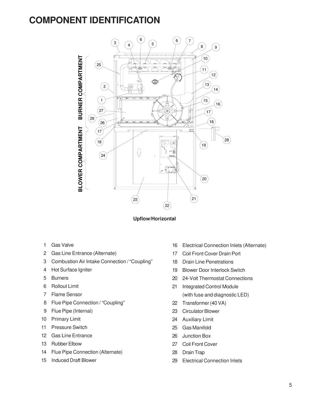
| Upflow/Horizontal |
|
| |
1 | Gas Valve | 16 | Electrical Connection Inlets (Alternate) |
2 | Gas Line Entrance (Alternate) | 17 | Coil Front Cover Drain Port |
3 | Combustion Air Intake Connection / “Coupling” | 18 | Drain Line Penetrations |
4 | Hot Surface Igniter | 19 | Blower Door Interlock Switch |
5 | Burners | 20 | |
6 | Rollout Limit | 21 | Integrated Control Module |
7 | Flame Sensor |
| (with fuse and diagnostic LED) |
8 | Flue Pipe Connection / “Coupling” | 22 | Transformer (40 VA) |
9 | Flue Pipe (Internal) | 23 | Circulator Blower |
10 | Primary Limit | 24 | Auxiliary Limit |
11 | Pressure Switch | 25 | Gas Manifold |
12 | Gas Line Entrance | 26 | Junction Box |
13 | Rubber Elbow | 27 | Coil Front Cover |
14 | Flue Pipe Connection (Alternate) | 28 | Drain Trap |
15 | Induced Draft Blower | 29 | Electrical Connection Inlets |
5