WIRING DIAGRAMS

GMS8

WARNING:DISCONNECT POWER BEFORE SERVICING.WIRING TO UNIT MUST BE PROPERLY POLARIZED AND GROUNDED.

HUMIDIFIER

INTEGRATED


CONTROL MODULE

XFMR (6)

GND

INSTALLING THIS FAILURE TO INJURY OR DEATH.

24VAC

HUMIDIFIER

C

G

R W

FUSE


3

2

1


6

5

4


9

8

7


12

11

10

BL


RD


RD

2


GR


1


BL


PU


BK


PU

BK


Y

DIAGNOSTIC

LED

OR

YL

RD

YL

BR

INTEGRATED

CONTROL MODULE 115VAC

NEUTRAL

OR

YL

WH

YL

RD


WH

115 VAC HOT AND PARK TERMINALS


LINE-H XFMR-H

HEAT-HCOOL-H


AUXILIARY

LIMITS

BR

BK (HI) BL (MED) OR (MED LOW) RD (LOW) WH (N)


GND (8)


MVC (9)


C2 GAS


VALVE


MV (12)


M1


C


ID BLOWER


AUXILIARY

PRESSURE


24V


LIMITCONTROLS

SWITCH


G


PS (10)

C

NO


THERMOSTAT

Y

TO

PSO (4)


MICRO

HLI (7)


W


HLO (1)


CONNECTIONS


AUTO RESET

R


PRIMARY


RO2 (11)


LIMIT


CONTROL


RO1 (5)


MANUAL RESET ROLLOUT


LIMIT CONTROL(S)


XFMR (3)

(SINGLE CONTROL ON SOME MODELS)


24 VAC


40 VA


TRANSFORMER


XFMR-H


115 VAC

XFMR-N


FLAME SENSOR


FP (2)

HOT SURFACE


IGNITER


IGN


IGN-N

INTEGRATEDCONTROL

INTEGRATED


ID


IND


BLWR

IND-N


COOL-H


HIGH VOLTAGE! DISCONNECT ALL POWER BEFORE SERVICING OR UNIT. MULTIPLE POWER SOURCES MAY BE PRESENT. DO SO MAY CAUSE PROPERTY DAMAGE, PERSONAL

24V

BK


WH

RD

OR

YL

BR

CICULATORBLOWER

CAP

BR BR


BK


WH


115V


YL


XFMR


WH


GR


WH


15 PIN PLUG


ON SOME MODELS


BLOWER COMPARTMENT


BURNER COMPARTMENT


DOOR SWITCH


BK


24 VAC


HUMIDIFIER


SWITCH LOCATED IN BLOWER


COMPARTMENT ON SOME MODELS


YL

NO

C


OR


RD

RD


PRESSURE

YL

BK


PRIMARY LIMIT


WH


SWITCH


WH


WH


BK


BR


BL


OR


BK


HOT

M1

C2


W

H


SURFACE


FLAME


IGNITER


SENSOR


GAS VALVE


PU

INDUCED DRAFT

BLOWER

PU PU

ROLLOUT LIMITS

(SINGLE CONTROL ON SOME MODELS)

CONTROLMODULE

C


O


OL


MODULE


CIRCULATOR


BLWR

CIR-N


T


A


E


H


HEAT-H


LINE-H


LINE-N


JUNCTION BOX


DOOR


SWITCH


WARNING:


DISCONNECT POWER


DISCONNECT


BEFORE SERVICING.


WIRING TO UNIT


MUST BE


PROPERLY


POLARIZED


AND GROUNDED.


L

GND

N


TO 115VAC/

1 Ø /60 HZ POWER SUPPLY WITH


OVERCURRENT PROTECTION DEVICE

JUNCTION

BOX

LINE-N

GND

LINE H

TO 115 VAC/ 1/60HZ

POWER SUPPLY WITH

OVERCURRENT PROTECTION

DEVICE

0

STEADY ON

= NORMAL OPERATION


OFF

= CONTROL FAILURE

1

1 FLASH

= SYSTEM LOCKOUT (RETRIES/RECYCLES EXCEEDED)

2

2 FLASHES

= PRESSURE SWITCH STUCK CLOSED

3

3 FLASHES

= PRESSURE SWITCH STUCK OPEN

4

4 FLASHES

= OPEN HIGH LIMIT

5

5 FLASHES

= FLAME SENSE WITHOUT GAS VALVE

6

6 FLASHES

= OPEN ROLLOUT

7

7 FLASHES

= LOW FLAME SIGNAL

C RAPID FLASHES = REVERSED 115 VAC POLARITY/VERIFY GND

LOW VOLTAGE (24V)

LOW VOLTAGE FIELD

HI VOLTAGE (115V)

HI VOLTAGE FIELD

JUNCTION

TERMINAL

INTERNAL TO INTEGRATED CONTROL

PLUG CONNECTION

EQUIPMENT GND

FIELD GND

FIELD SPLICE

SWITCH (TEMP.)

IGNITER

SWITCH (PRESS.)

OVERCURRENT PROT. DEVICE

COLOR CODES:

PK PINK

NOTES:

1. SET HEAT ANTICIPATOR ON ROOM THERMOSTAT AT 0.7 AMPS.

YL YELLOW

BR BROWN

2. MANUFACTURER'S SPECIFIED REPLACEMENT PARTS MUST BE USED WHEN SERVICING.

OR ORANGE

WH WHITE

3. IF ANY OF THE ORIGINAL WIRE AS SUPPLIED WITH THE FURNACE MUST BE

PU PURPLE

BL BLUE

REPLACED, IT MUST BE REPLACED WITH WIRING MATERIAL HAVING A TEMPERATURE

GR GREEN

GY GRAY

RATING OF AT LEAST 105 C. USE COPPER CONDUCTORS ONLY.

4. BLOWER SPEEDS MUST BE ADJUSTED BY INSTALLER TO MATCH THE INSTALLATION

BK BLACK

RD RED

REQUIREMENTS SO AS TO PROVIDE THE CORRECT HEATING TEMPERATURE RISE AND THE


CORRECT COOLING CFM. (SEE SPEC SHEET FOR AIR FLOW CHART)


5. UNIT MUST BE PERMANENTLY GROUNDED AND CONFORM TO N.E.C. AND LOCAL CODES.

0140F00119-C

Wiring is subject to change, always refer to the wiring diagram on the unit for the most up-to-date wiring.

12

Page 12
Image 12
Goodman Mfg RT6621031r2, GMS8 33-3/8 GAS FURNACE UNITS Wiring Diagrams GMS8, Installing this Failure to Injury or Death

RT6621031r2, GMS8 33-3/8 GAS FURNACE UNITS specifications

Goodman Manufacturing is renowned for delivering reliable and efficient HVAC systems, and the RT6621031R2 GMS8 Gas Furnace is no exception. This gas furnace is specifically engineered for residential heating needs, ensuring comfort in various climates. Its design is both effective and energy-efficient, making it a popular choice among homeowners.

One of the main features of the GMS8 furnace is its two-stage heating capability. This technology allows the unit to operate at two different levels of heating output, which helps maintain a more consistent temperature within the home. During milder temperatures, the furnace can operate at a lower stage, saving energy while still delivering adequate warmth. On colder days, it seamlessly transitions to the higher stage, ensuring maximum comfort.

The GMS8 boasts a multi-speed blower motor, which enhances its overall efficiency and performance. This allows for variable airflow adjustments, improving air distribution throughout the home. The result is not only increased comfort but also reduced noise levels, making the operation of this furnace pleasantly quiet.

An important characteristic of the GMS8 is its durable construction, featuring a heavy-gauge steel cabinet designed to withstand harsh operating conditions. The integrated insulated blower compartment further ensures that the unit operates efficiently while minimizing heat loss. Its compact design allows for easier installation in various home configurations.

In terms of energy efficiency, the GMS8 is equipped with a 80% Annual Fuel Utilization Efficiency (AFUE) rating. This means that 80% of the gas consumed translates into usable heat, making it a cost-effective option for heating your home. Additionally, it is compatible with a range of programmable thermostats, allowing homeowners to optimize their heating schedules and further enhance energy savings.

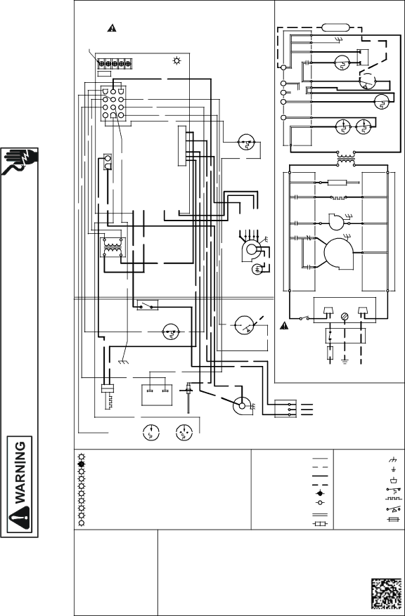
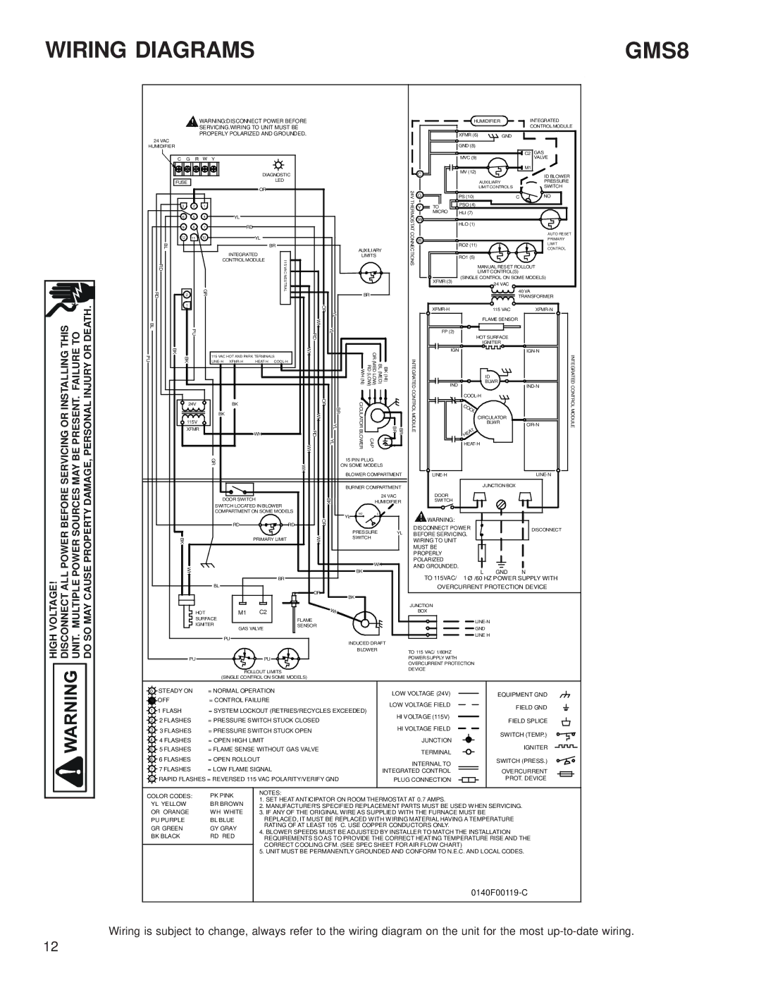
The GMS8 furnace is also designed with safety in mind. It includes features such as an integrated self-diagnostic control board and a flame rollout switch for enhanced operational safety. The extended warranty options available also provide peace of mind, ensuring that homeowners feel secure in their investment.

In summary, the Goodman RT6621031R2 GMS8 Gas Furnace is an efficient, reliable, and durable heating solution for homes. With its two-stage heating capabilities, multi-speed blower motor, and a robust design, it stands out as a trusted choice for families seeking comfort and energy savings during the chilly months.