
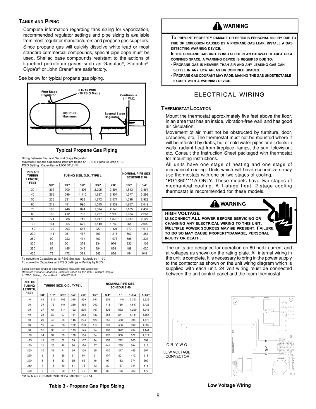
GPG13 specifications
Goodman Manufacturing is a prominent name in the HVAC industry, known for providing high-quality heating and cooling systems. Among their diverse lineup, the Goodman GPG13 stands out as a reliable packaged gas/electric unit. This model is particularly designed for residential and light commercial applications, ensuring a perfect blend of efficiency, comfort, and affordability.One of the primary features of the Goodman GPG13 is its energy efficiency. The unit has a Seasonal Energy Efficiency Ratio (SEER) rating that helps homeowners reduce their energy costs while providing optimal cooling performance during warmer months. With a cooling capacity ranging from 2.5 to 5 tons, it effectively meets the cooling requirements of various sizes of homes or commercial spaces.
The Goodman GPG13 employs advanced technology to guarantee reliable operation. Its quiet operation is a significant advantage, thanks to the sound-dampening design of the unit’s compressor and fan. Moreover, the unit is equipped with a high-efficiency scroll compressor, which is known for its durability and consistent performance. This technology not only enhances the unit’s longevity but also ensures that homeowners enjoy a peaceful indoor environment.
In terms of construction, the Goodman GPG13 is built to last. The unit features a heavy-gauge galvanized steel cabinet with a powder-coated finish, which protects it from the elements and corrosion. This sturdy design ensures that the GPG13 can withstand various environmental conditions without compromising performance. Additionally, it has an easy-access control panel, simplifying maintenance and servicing tasks.
Another noteworthy characteristic of the Goodman GPG13 is its environmentally friendly refrigerant, R-410A. Unlike older refrigerants, R-410A has a lower environmental impact and contributes to ozone layer protection. This focus on environmental responsibility is essential in today’s green-conscious society and reflects Goodman’s commitment to sustainable practices.
The GPG13 is also equipped with a reliable multi-speed blower motor that enhances comfort by providing consistent airflow throughout the space. This capability allows homeowners to maintain desired temperatures while maximizing energy savings.
Overall, the Goodman GPG13 packaged gas/electric unit is an excellent choice for those seeking efficiency, durability, and comfort in their heating and cooling systems. With its range of advanced features and technologies, it stands as a testament to Goodman Manufacturing's dedication to quality and customer satisfaction in HVAC solutions.