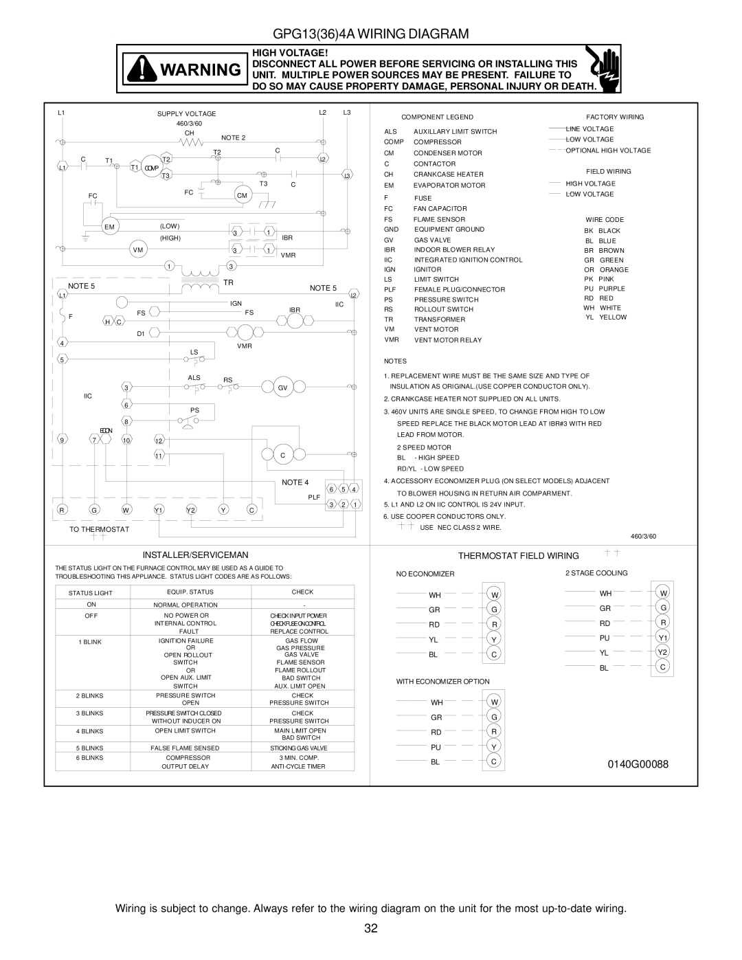
GPG13(36)4A WIRING DIAGRAM


HIGH VOLTAGE!


DISCONNECT ALL POWER BEFORE SERVICING OR INSTALLING THIS


UNIT. MULTIPLE POWER SOURCES MAY BE PRESENT. FAILURE TO


DO SO MAY CAUSE PROPERTY DAMAGE, PERSONAL INJURY OR DEATH.


L1


SUPPLY VOLTAGE


L2

L3


COMPONENT LEGEND

FACTORY WIRING


460/3/60


ALS

AUXILLARY LIMIT SWITCH

LINE VOLTAGE


CH


NOTE 2


LOW VOLTAGE


COMP

COMPRESSOR


C


OPTIONAL HIGH VOLTAGE

C

T1


T2

T2


CM

CONDENSER MOTOR

T1


L2


C

CONTACTOR


L1


COMP


FIELD WIRING


CH

CRANKCASE HEATER


T3


L3


T3


HIGH VOLTAGE


FC


C


EM

EVAPORATOR MOTOR


FC


CM


F

FUSE

LOW VOLTAGE


FC

FAN CAPACITOR


EM


(LOW)


FS

FLAME SENSOR

WIRE CODE


3

1


GND

EQUIPMENT GROUND

BK

BLACK


(HIGH)


IBR


GV

GAS VALVE

BL

BLUE


VM


3

1

VMR


IBR

INDOOR BLOWER RELAY

BR

BROWN


IIC

INTEGRATED IGNITION CONTROL

GR

GREEN


1


3


IGN

IGNITOR

OR

ORANGE


NOTE 5


TR


LS

LIMIT SWITCH

PK

PINK


NOTE 5


PLF

FEMALE PLUG/CONNECTOR

PU

PURPLE


L1


L2


IGN


PS

PRESSURE SWITCH

RD

RED


IIC


IBR


RS

ROLLOUT SWITCH

WH

WHITE

F


FS


FS


TR

TRANSFORMER

YL

YELLOW

H

C


VM

VENT MOTOR


D1


VMR

VENT MOTOR RELAY


4


VMR


LS


5


NOTES


ALS

RS


1. REPLACEMENT WIRE MUST BE THE SAME SIZE AND TYPE OF


3


GV


INSULATION AS ORIGINAL.(USE COPPER CONDUCTOR ONLY).


IIC


2. CRANKCASE HEATER NOT SUPPLIED ON ALL UNITS.


6


PS


3. 460V UNITS ARE SINGLE SPEED, TO CHANGE FROM HIGH TO LOW


ECON

8


SPEED REPLACE THE BLACK MOTOR LEAD AT IBR#3 WITH RED


LEAD FROM MOTOR.


9

7

10

12


2 SPEED MOTOR


11


C


BL

- HIGH SPEED


RD/YL - LOW SPEED


NOTE 4


4. ACCESSORY ECONOMIZER PLUG (ON SELECT MODELS) ADJACENT


6

5

4

TO BLOWER HOUSING IN RETURN AIR COMPARMENT.


PLF


5. L1 AND L2 ON IIC CONTROL IS 24V INPUT.


R

G

W

Y1

Y2

Y

C

3

2

1


6. USE COOPER CONDUCTORS ONLY.


TO THERMOSTAT


USE NEC CLASS 2 WIRE.


460/3/60


INSTALLER/SERVICEMAN


THERMOSTAT FIELD WIRING


THE STATUS LIGHT ON THE FURNACE CONTROL MAY BE USED AS A GUIDE TO


NO ECONOMIZER


2 STAGE COOLING

TROUBLESHOOTING THIS APPLIANCE. STATUS LIGHT CODES ARE AS FOLLOWS:


STATUS LIGHT

EQUIP. STATUS

CHECK


WH


W


WH


W


ON

NORMAL OPERATION

-


GR


G


GR


G


OFF

NO POWER OR

CHECK INPUT POWER


R


INTERNAL CONTROL

CHECK FUSE ON CONTROL


RD


R


RD


FAULT

REPLACE CONTROL


PU


Y1

1 BLINK

IGNITION FAILURE

GAS FLOW


YL


Y


OR

GAS PRESSURE


YL


Y2


OPEN ROLLOUT

GAS VALVE


BL


C


SWITCH

FLAME SENSOR


BL


C


OR

FLAME ROLLOUT


OPEN AUX. LIMIT

BAD SWITCH


WITH ECONOMIZER OPTION


SWITCH

AUX. LIMIT OPEN


2 BLINKS

PRESSURE SWITCH

CHECK


W


OPEN

PRESSURE SWITCH


WH


3 BLINKS

PRESSURE SWITCH CLOSED

CHECK


GR


G


WITHOUT INDUCER ON

PRESSURE SWITCH


4 BLINKS

OPEN LIMIT SWITCH

MAIN LIMIT OPEN


RD


R


BAD SWITCH


5 BLINKS

FALSE FLAME SENSED

STICKING GAS VALVE


PU


Y


6 BLINKS

COMPRESSOR

3 MIN. COMP.


BL


C


0140G00088


OUTPUT DELAY

ANTI-CYCLE TIMER


Wiring is subject to change. Always refer to the wiring diagram on the unit for the most up-to-date wiring.

32

Page 32
Image 32
Goodman Mfg GPG13 installation manual 0140G00088

GPG13 specifications

Goodman Manufacturing is a prominent name in the HVAC industry, known for providing high-quality heating and cooling systems. Among their diverse lineup, the Goodman GPG13 stands out as a reliable packaged gas/electric unit. This model is particularly designed for residential and light commercial applications, ensuring a perfect blend of efficiency, comfort, and affordability.

One of the primary features of the Goodman GPG13 is its energy efficiency. The unit has a Seasonal Energy Efficiency Ratio (SEER) rating that helps homeowners reduce their energy costs while providing optimal cooling performance during warmer months. With a cooling capacity ranging from 2.5 to 5 tons, it effectively meets the cooling requirements of various sizes of homes or commercial spaces.

The Goodman GPG13 employs advanced technology to guarantee reliable operation. Its quiet operation is a significant advantage, thanks to the sound-dampening design of the unit’s compressor and fan. Moreover, the unit is equipped with a high-efficiency scroll compressor, which is known for its durability and consistent performance. This technology not only enhances the unit’s longevity but also ensures that homeowners enjoy a peaceful indoor environment.

In terms of construction, the Goodman GPG13 is built to last. The unit features a heavy-gauge galvanized steel cabinet with a powder-coated finish, which protects it from the elements and corrosion. This sturdy design ensures that the GPG13 can withstand various environmental conditions without compromising performance. Additionally, it has an easy-access control panel, simplifying maintenance and servicing tasks.

Another noteworthy characteristic of the Goodman GPG13 is its environmentally friendly refrigerant, R-410A. Unlike older refrigerants, R-410A has a lower environmental impact and contributes to ozone layer protection. This focus on environmental responsibility is essential in today’s green-conscious society and reflects Goodman’s commitment to sustainable practices.

The GPG13 is also equipped with a reliable multi-speed blower motor that enhances comfort by providing consistent airflow throughout the space. This capability allows homeowners to maintain desired temperatures while maximizing energy savings.

Overall, the Goodman GPG13 packaged gas/electric unit is an excellent choice for those seeking efficiency, durability, and comfort in their heating and cooling systems. With its range of advanced features and technologies, it stands as a testament to Goodman Manufacturing's dedication to quality and customer satisfaction in HVAC solutions.