TROUBLESHOOTING GUIDE
WARNING
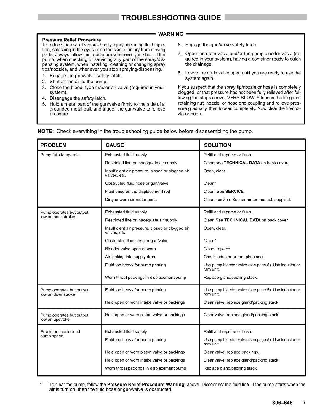
Pressure Relief Procedure | 6. Engage the gun/valve safety latch. | ||
To reduce the risk of serious bodily injury, including fluid injec- | |||
tion, splashing in the eyes or on the skin, or injury from moving | 7. Open the drain valve and/or the pump bleeder valve (re- | ||
parts, always follow this procedure whenever you shut off the | |||
pump, when checking or servicing any part of the spray/dis- | quired in your system), having a container ready to catch | ||
pensing system, when installing, cleaning or changing spray | the drainage. | ||
tips/nozzles, and whenever you stop spraying/dispensing. | 8. Leave the drain valve open until you are ready to use the | ||
1. | Engage the gun/valve safety latch. | ||
system again. | |||
2. | Shut off the air to the pump. | ||
If you suspect that the spray tip/nozzle or hose is completely | |||
3. | Close the | ||
| system). | clogged, or that pressure has not been fully relieved after fol- | |
4. | Disengage the safety latch. | lowing the steps above, VERY SLOWLY loosen the tip guard | |
5. | Hold a metal part of the gun/valve firmly to the side of a | retaining nut, nozzle, or hose end coupling and relieve pres- | |
| grounded metal pail, and trigger the gun/valve to relieve | sure gradually, then loosen completely. Now clear the tip/noz- | |
| pressure. | zle or hose. | |
NOTE: Check everything in the troubleshooting guide below before disassembling the pump.
PROBLEM | CAUSE | SOLUTION |
|
|
|
Pump fails to operate | Exhausted fluid supply | Refill and reprime or flush. |
| Restricted line or inadequate air supply | Clear; see TECHNICAL DATA on back cover. |
| Insufficient air pressure, closed or clogged air | Open, clear. |
| valves, etc. |
|
| Obstructed fluid hose or gun/valve | Clear.* |
| Fluid dried on the displacement rod | Clean. See SERVICE. |
| Dirty or worn air motor parts | Clean, service. See air motor manual, supplied. |
|
|
|
Pump operates but output | Exhausted fluid supply | Refill and reprime or flush. |
low on both strokes | Restricted line or inadequate air supply | Clear. See TECHNICAL DATA on back cover. |
| ||
| Insufficient air pressure, closed or clogged air | Open, clear. |
| valves, etc. |
|
| Obstructed fluid hose or gun/valve | Clear.* |
| Bleeder valve open or worn | Close; replace. |
| Air leaking into supply drum | Check inductor or ram plate seal. |
| Fluid too heavy for pump priming | Use pump bleeder valve (see page 5). Use inductor or |
|
| ram unit. |
| Worn throat packings in displacement pump | Replace gland/packing stack. |
|
|
|
Pump operates but output | Fluid too heavy for pump priming | Use pump bleeder valve (see page 5). Use inductor or |
low on downstroke |
| ram unit. |
| Held open or worn intake valve or packings | Clear valve; replace gland/packing stack. |
|
|
|
Pump operates but output | Held open or worn piston valve or packings | Clear valve; replace gland/packing stack. |
low on upstroke |
|
|
|
|
|
Erratic or accelerated | Exhausted fluid supply | Refill and reprime or flush. |
pump speed | Fluid too heavy for pump priming | Use pump bleeder valve (see page 5). Use inductor or |
| ||
|
| ram unit. |
| Held open or worn piston valve or packings | Clear valve; replace packings. |
| Held open or worn intake valve or packings | Clear valve; replace gland/packing stack. |
| Worn throat packings in displacement pump | Replace gland/packing stack. |
|
|
|
*To clear the pump, follow the Pressure Relief Procedure Warning, above. Disconnect the fluid line. If the pump starts when the air is turn on, then the fluid hose or gun/valve is obstructed.