Components Mounting Bracket
During system installation,
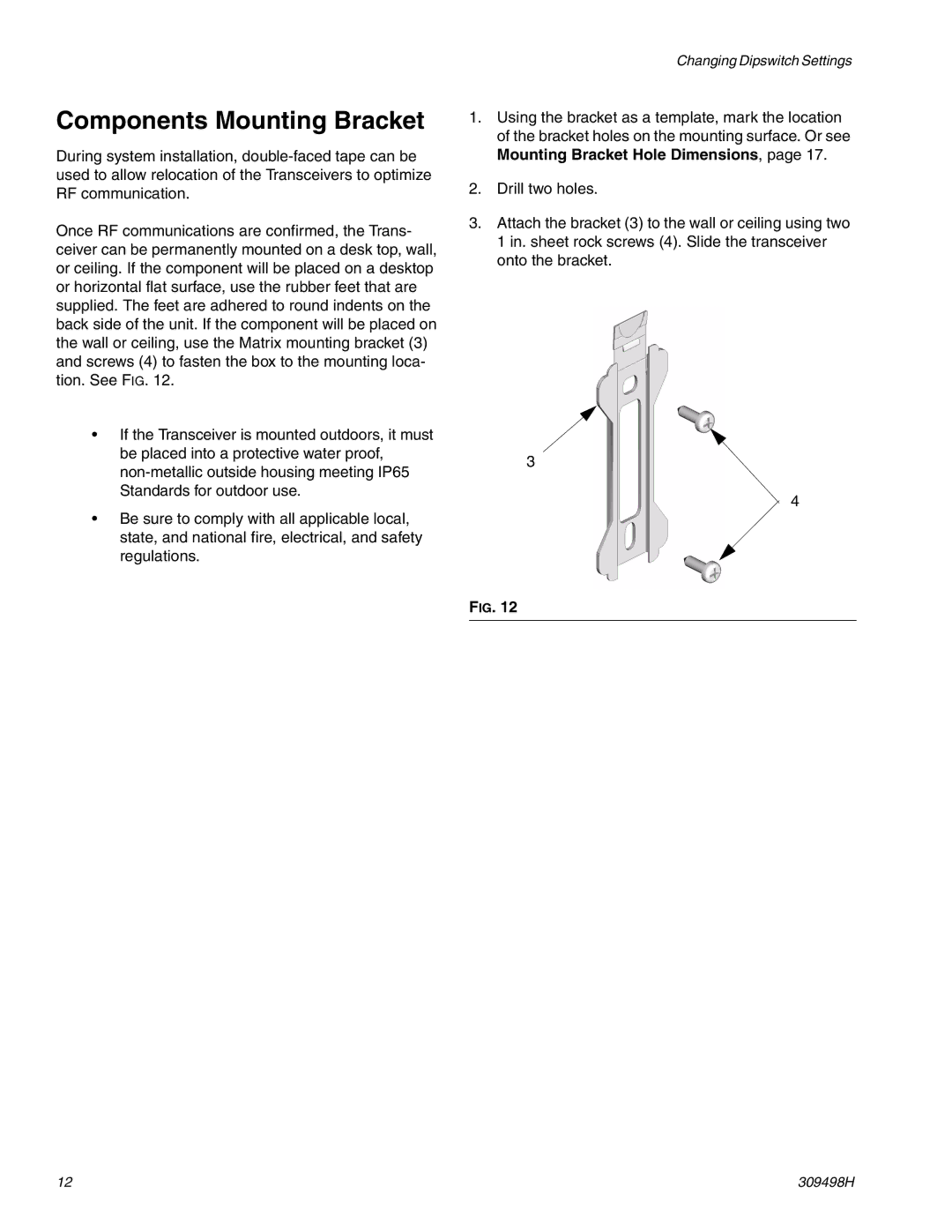
Once RF communications are confirmed, the Trans- ceiver can be permanently mounted on a desk top, wall, or ceiling. If the component will be placed on a desktop or horizontal flat surface, use the rubber feet that are supplied. The feet are adhered to round indents on the back side of the unit. If the component will be placed on the wall or ceiling, use the Matrix mounting bracket (3) and screws (4) to fasten the box to the mounting loca- tion. See FIG. 12.
•If the Transceiver is mounted outdoors, it must be placed into a protective water proof,
•Be sure to comply with all applicable local, state, and national fire, electrical, and safety regulations.
Changing Dipswitch Settings
1.Using the bracket as a template, mark the location of the bracket holes on the mounting surface. Or see Mounting Bracket Hole Dimensions, page 17.
2.Drill two holes.
3.Attach the bracket (3) to the wall or ceiling using two 1 in. sheet rock screws (4). Slide the transceiver onto the bracket.
3
4
FIG. 12
12 | 309498H |