Changing Dipswitch Settings
Changing Dipswitch Settings
Network ID and Transceiver ID dipswitch settings are made on the PC board. To access the board, the trans- ceiver cover must be removed.
1. Remove power to the transceiver.
All dipswitch settings must be made without power to the transceiver.
Removing the Transceiver Cover
When necessary to change dipswitch settings remove the transceiver cover by:
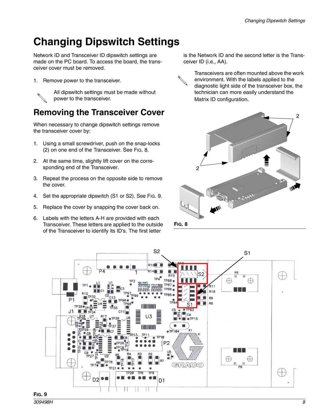
1.Using a small screwdriver, push on the
(2) on one end of the Transceiver. See FIG. 8.
2.At the same time, slightly lift cover on the corre- sponding end of the Transceiver.
3.Repeat the process on the opposite side to remove the cover.
4.Set the appropriate dipswitch (S1 or S2). See FIG. 9.
5.Replace the cover by snapping the cover back on.
6.Labels with the letters
is the Network ID and the second letter is the Trans- ceiver ID (i.e., AA).
Transceivers are often mounted above the work environment. With the labels applied to the diagnostic light side of the transceiver box, the technician can more easily understand the Matrix ID configuration.
2
2
FIG. 8
S2 | S1 |
|
FIG. 9
309498H | 9 |