CC Operation

For CC operation, the current setting of each output must be programmed to the desired operating current. The sum of the voltage settings determines the voltage limit point. As an example, one way to program the voltage of the output is to set the voltage of each output to one half of the total voltage limit point. Then, at load voltages less than one half of the total voltage limit point, one output will operate in CC mode while the other output will be conducting through its internal reverse voltage protection diode. At load voltages greater than one half the total voltage limit point, the output that was in

CCmode will change to CV mode while the output that was conducting through its diode will regulate the current in CC mode and provide the balance of the voltage required by the load. Note that the total load voltage can be found by adding the results of reading back the individual series outputs only when neither reverse voltage protection diode is conducting. When this diode is conducting, the corresponding output has reverse voltage across it so that its voltage readback may not be accurate.

When an output is conducting through its reverse voltage protection diode, the output will have a reverse voltage across its output terminals with the - V terminal more positive than the + V terminal. This voltage will be I maximum at the rated current of the output. (See Figure 4-2 for reverse diode characteristic). Note that when an output conducts through this diode, it will indicate CC mode even though it is not regulating the current or voltage. Also, note that the voltage readback is not specified to indicate negative voltages although it will operate down to a limit of about - .22 V on the low voltage outputs and -.52 V on the high voltage outputs. These values will still be indicated even if the actual voltage is more negative.

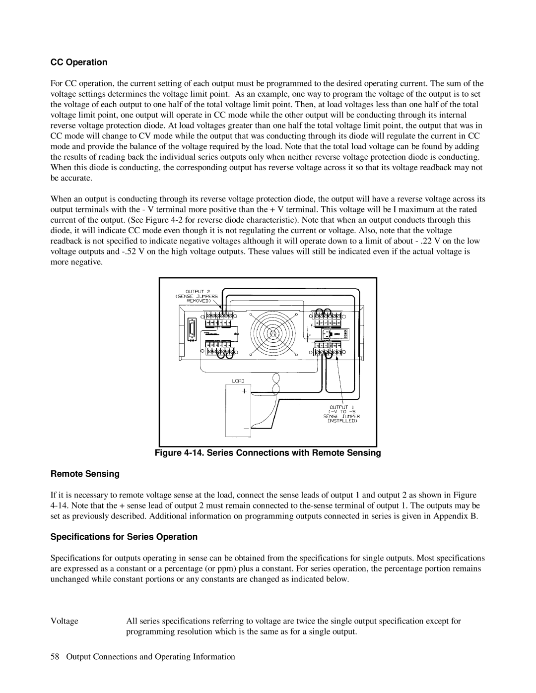
Figure 4-14. Series Connections with Remote Sensing

Remote Sensing

If it is necessary to remote voltage sense at the load, connect the sense leads of output 1 and output 2 as shown in Figure 4-14. Note that the + sense lead of output 2 must remain connected to the-sense terminal of output 1. The outputs may be set as previously described. Additional information on programming outputs connected in series is given in Appendix B.

Specifications for Series Operation

Specifications for outputs operating in sense can be obtained from the specifications for single outputs. Most specifications are expressed as a constant or a percentage (or ppm) plus a constant. For series operation, the percentage portion remains unchanged while constant portions or any constants are changed as indicated below.

Voltage

All series specifications referring to voltage are twice the single output specification except for


programming resolution which is the same as for a single output.

58 Output Connections and Operating Information

Page 58
Image 58
HP 6624A, 6623A, 6621A manual Series Connections with Remote Sensing, Specifications for Series Operation

6624A, 6621A, 6623A specifications

The HP 6623A, 6621A, and 6624A are precision DC power supplies widely recognized for their reliability and performance in various laboratory and industrial applications. These models are part of HP's 662X series, designed to cater to the needs of engineers, researchers, and technicians who require accurate power sources for their testing and development activities.

The main features of the HP 6623A, 6621A, and 6624A include their high stability, low ripple, and excellent load regulation, ensuring that the output voltage and current remain stable during testing. The power supplies provide multiple output channels, allowing users to power multiple devices simultaneously. The flexibility in setting voltage and current levels makes these models ideal for a wide range of applications, including semiconductor testing, device characterization, and system integration.

One of the standout technologies in the HP 662X series is the use of smart design techniques that minimize noise and enhance output performance. These power supplies incorporate advanced feedback mechanisms to maintain steady output, even under varying load conditions. Additionally, they feature programmable outputs, which means users can adjust the output levels through a connected computer or control system, streamlining the testing process and improving efficiency.

The HP 6623A model offers three independent outputs, with total power capabilities of 40 watts. It includes a 0-20V output, which can deliver up to 2A of current, along with two additional outputs that are adjustable. The 6621A provides a single output option, delivering a maximum of 20V and 2A, making it well-suited for simple applications where a single power source is required. In contrast, the HP 6624A stands out with its four independent output channels, providing a total of 60 watts, making it the most versatile of the three models.

Characteristics of these power supplies include user-friendly interfaces, allowing for easy configuration and monitoring of settings. LED indicators provide real-time feedback on voltage and current levels, enabling users to quickly assess the performance of their tests. Moreover, built-in protection features safeguard both the power supply and the connected devices from overvoltage and overcurrent conditions.

Overall, the HP 6623A, 6621A, and 6624A power supplies embody advanced engineering and design, making them invaluable tools for professionals looking for high-quality, reliable power sources for their electronic testing needs.