The Mask and Fault Register. The fault register works in conjunction with the mask register. These are two eight bit registers which report any fault condition on a particular output channel. The mask register is used to set up the conditions that generate a fault which is latched into the fault register. The user can then read the fault register to determine the fault. When a bit in the fault register is set, the power supply can generate a service request for that output providing the service request command on fault (SRQ 1 or SRQ 3) was previously sent. See page 76 for a discussion on service request.

To understand how these two registers work, we must include the status register in this discussion. Recall that the status register takes its input from the power supply and the user cannot change its contents. The mask register takes its inputs from the user, and the power supply cannot change its contents. The fault register takes its inputs from both the mask and the status registers. You can find out the setting of the mask register of output 2 by sending the following query and addressing the supply to talk:

UNMASK? 2

The response will be a numeric code between 0 and 255 which can be decoded by consulting Table 5-5. You can set the conditions to generate a fault by setting (unmasking) one or more bits in the mask register. The conditions will remain unmasked until you change them. To unmask conditions in output 2 for example, send the following command:

UNMASK 2,XXX

where XXX specifies the numeric code (0 to 255) for the unmasked conditions (see Table 5-5). If during operation, the output experiences any of the previously unmasked conditions, it will set the corresponding bit(s) in its fault register.

Remember that the bits in the fault register can be set when there is a change in either the status register or the mask register. Each output has its status, mask, and fault registers arranged as shown in Figure 5-3 and Table 5-5. The mask register, which is set by the user, is used to specify which bits in the status register are enabled (unmasked) to set bits in the fault register. A bit is set in the fault register when the corresponding bit in the status register changes from "0'' to "1" and the corresponding bit in the mask register is a "1". Also, if a bit in the status register is already set and then the corresponding bit in the mask register is set (unmasked), the corresponding bit in the fault register will be set.

In addition, if both status and mask register bits remain set after the fault register was read (and cleared), the fault register will remain cleared as long as there are no changes in either the status or mask registers with the following exception. Executing a VSET, ISET, RCL, OVRST, OCRST, or OUT on/off command, will cause the CV, + CC, - CC, or UNR bit (as applicable) in the fault register to be set. Note that the fault register is cleared immediately after it is read.

As shown in Figure 5-3, if one or more bits in the fault register of a given output channel are set, then the FAU bit for that output in the serial poll register will also be set and a service request may be generated (see page 76). To read the fault register of output 2 and find out which bits are set, send the following query and address the supply to talk:

FAULT? 2

The power supply responds with a number which can be decoded from Table 5-5. For example, the number 9 (8 + 1) indicates that the OV and the CV bits in the fault register are set.

NOTE

If the condition(s) generating the fault(s) is (are) removed but the fault register is not read, the bit(s) in


the fault register will remain set.

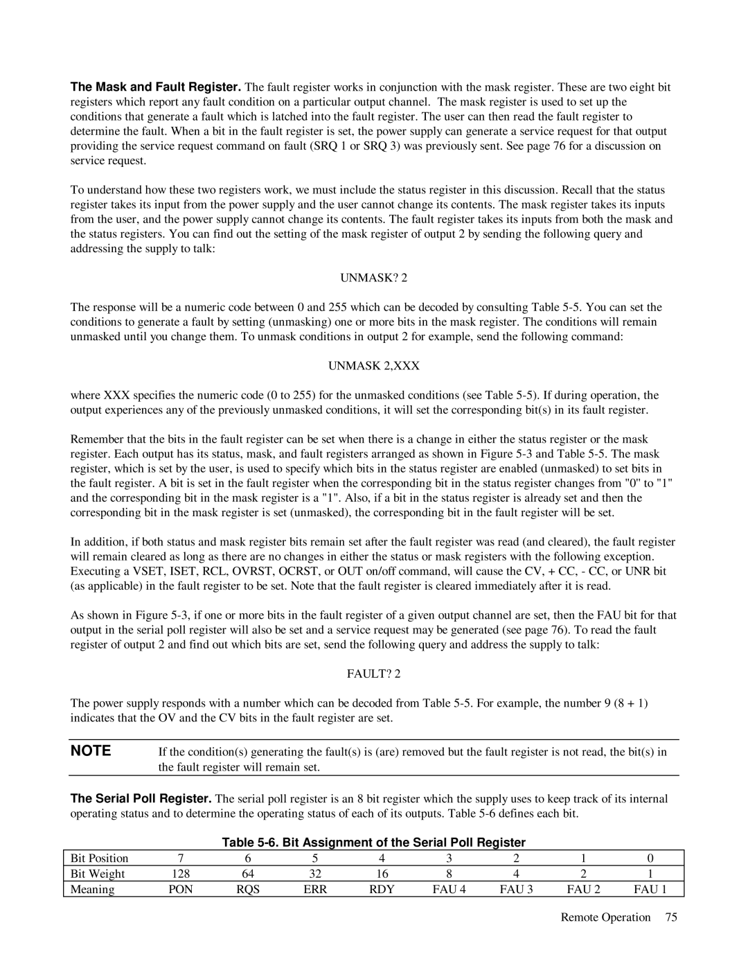
The Serial Poll Register. The serial poll register is an 8 bit register which the supply uses to keep track of its internal operating status and to determine the operating status of each of its outputs. Table 5-6 defines each bit.

Table 5-6. Bit Assignment of the Serial Poll Register

Bit Position

7

6

5

4

3

2

1

0

Bit Weight

128

64

32

16

8

4

2

1

Meaning

PON

RQS

ERR

RDY

FAU 4

FAU 3

FAU 2

FAU 1

Remote Operation 75

Page 75
Image 75
HP 6623A, 6624A, 6621A manual Unmask?, Unmask 2,XXX, Fault?, Bit Assignment of the Serial Poll Register, Pon Rqs Err Rdy Fau

6624A, 6621A, 6623A specifications

The HP 6623A, 6621A, and 6624A are precision DC power supplies widely recognized for their reliability and performance in various laboratory and industrial applications. These models are part of HP's 662X series, designed to cater to the needs of engineers, researchers, and technicians who require accurate power sources for their testing and development activities.

The main features of the HP 6623A, 6621A, and 6624A include their high stability, low ripple, and excellent load regulation, ensuring that the output voltage and current remain stable during testing. The power supplies provide multiple output channels, allowing users to power multiple devices simultaneously. The flexibility in setting voltage and current levels makes these models ideal for a wide range of applications, including semiconductor testing, device characterization, and system integration.

One of the standout technologies in the HP 662X series is the use of smart design techniques that minimize noise and enhance output performance. These power supplies incorporate advanced feedback mechanisms to maintain steady output, even under varying load conditions. Additionally, they feature programmable outputs, which means users can adjust the output levels through a connected computer or control system, streamlining the testing process and improving efficiency.

The HP 6623A model offers three independent outputs, with total power capabilities of 40 watts. It includes a 0-20V output, which can deliver up to 2A of current, along with two additional outputs that are adjustable. The 6621A provides a single output option, delivering a maximum of 20V and 2A, making it well-suited for simple applications where a single power source is required. In contrast, the HP 6624A stands out with its four independent output channels, providing a total of 60 watts, making it the most versatile of the three models.

Characteristics of these power supplies include user-friendly interfaces, allowing for easy configuration and monitoring of settings. LED indicators provide real-time feedback on voltage and current levels, enabling users to quickly assess the performance of their tests. Moreover, built-in protection features safeguard both the power supply and the connected devices from overvoltage and overcurrent conditions.

Overall, the HP 6623A, 6621A, and 6624A power supplies embody advanced engineering and design, making them invaluable tools for professionals looking for high-quality, reliable power sources for their electronic testing needs.