Installation
Installation
1.Relieve all system pressure before installing the dis- pense valve.
GROUNDING
The equipment must be grounded to reduce the risk of static sparking. Static sparking can cause fumes to ignite or explode. Grounding provides an escape wire for the electric current.
2.Ground the gun through connection to a properly grounded fluid hose and pump. See your system manual for further information.
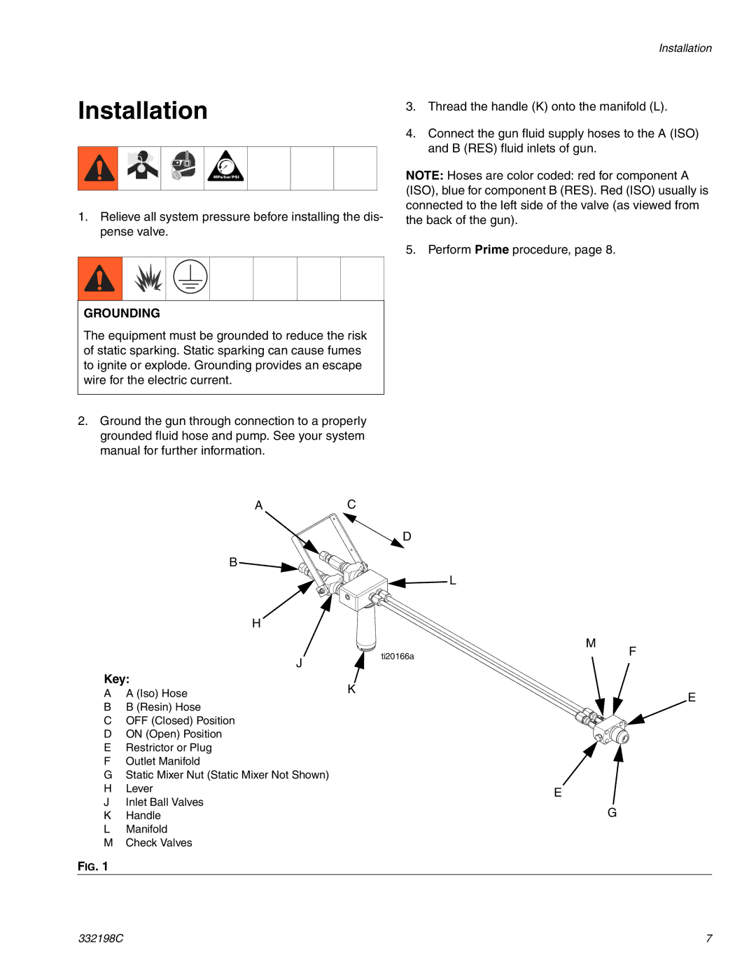
3.Thread the handle (K) onto the manifold (L).
4.Connect the gun fluid supply hoses to the A (ISO) and B (RES) fluid inlets of gun.
NOTE: Hoses are color coded: red for component A (ISO), blue for component B (RES). Red (ISO) usually is connected to the left side of the valve (as viewed from the back of the gun).
5. Perform Prime procedure, page 8.
A
B ![]()
H
J
Key:
AA (Iso) Hose
BB (Resin) Hose
COFF (Closed) Position
DON (Open) Position
ERestrictor or Plug
FOutlet Manifold
GStatic Mixer Nut (Static Mixer Not Shown)
HLever
JInlet Ball Valves
KHandle
LManifold
MCheck Valves
C
D
L
| M |
ti20166a | F |
|
K
E
E
G
FIG. 1
332198C | 7 |