Typical Installation Diagram
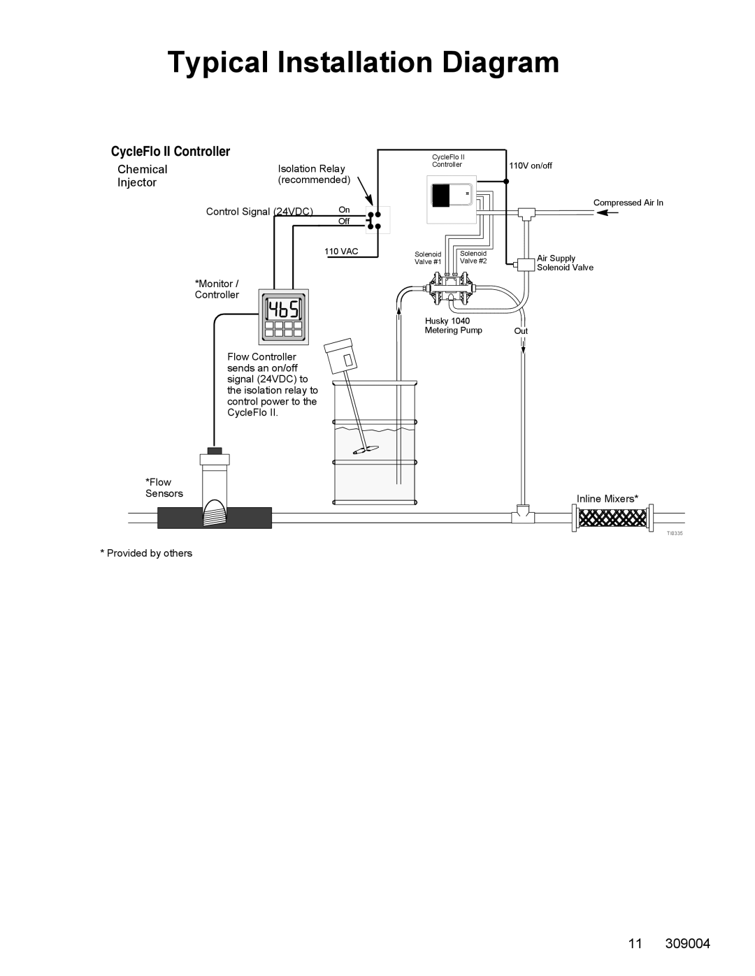
CycleFlo II Controller
Chemical | Isolation Relay | |
Injector | (recommended) | |
| Control Signal (24VDC) | On |
|
| Off |
|
| 110 VAC |
| *Monitor / |
|
| Controller |
|
Flow Controller sends an on/off signal (24VDC) to the isolation relay to control power to the CycleFlo II.
*Flow |
Sensors |
* Provided by others
CycleFlo II |
|
Controller | 110V on/off |
Compressed Air In
Solenoid | Solenoid | Air Supply |
Valve #1 | Valve #2 | |
|
| Solenoid Valve |
Husky 1040 |
| |
Metering Pump | Out | |
Inline Mixers*
TI0335
11 309004