Overview
|
| Hazardous Area |
| ||
|
|
|
| ||
F D E V | H | N M |
| M C B W A Z AB AA S | AC |
| |||||
| |||||
| |||||
|
|
|
| ||
|
|
|
| ||
|
|
|
| ||
|
|
|
| ||
|
|
|
| ||
|
|
|
| ||
Y
| L |
|
|
| ||
|
|
|
|
|
| AD |
|
|
|
|
|
| |
|
|
|
|
|
| T |
|
|
|
|
|
| |
|
|
|
| U | Hazardous | |
|
|
|
| |||
|
|
|
|
|
| |
|
|
|
|
|
| Area |
|
|
|
|
|
| |
G |
|
|
|
|
| Entrance |
|
|
|
|
| ||
|
|
|
|
|
| |
X |
|
| K |
|
|
|
|
|
|
|
| ||
|
|
|
|
|
| |
|
|
| J |
|
|
|
|
|
|
|
|
| |
|
|
| R | P AD |
| |
|
|
|
| |||
|
|
|
| |||
|
| Hazardous Area |
|
| ti8651c | |
|
|
|
| |||
|
|
|
| |||
|
|
|
| |||
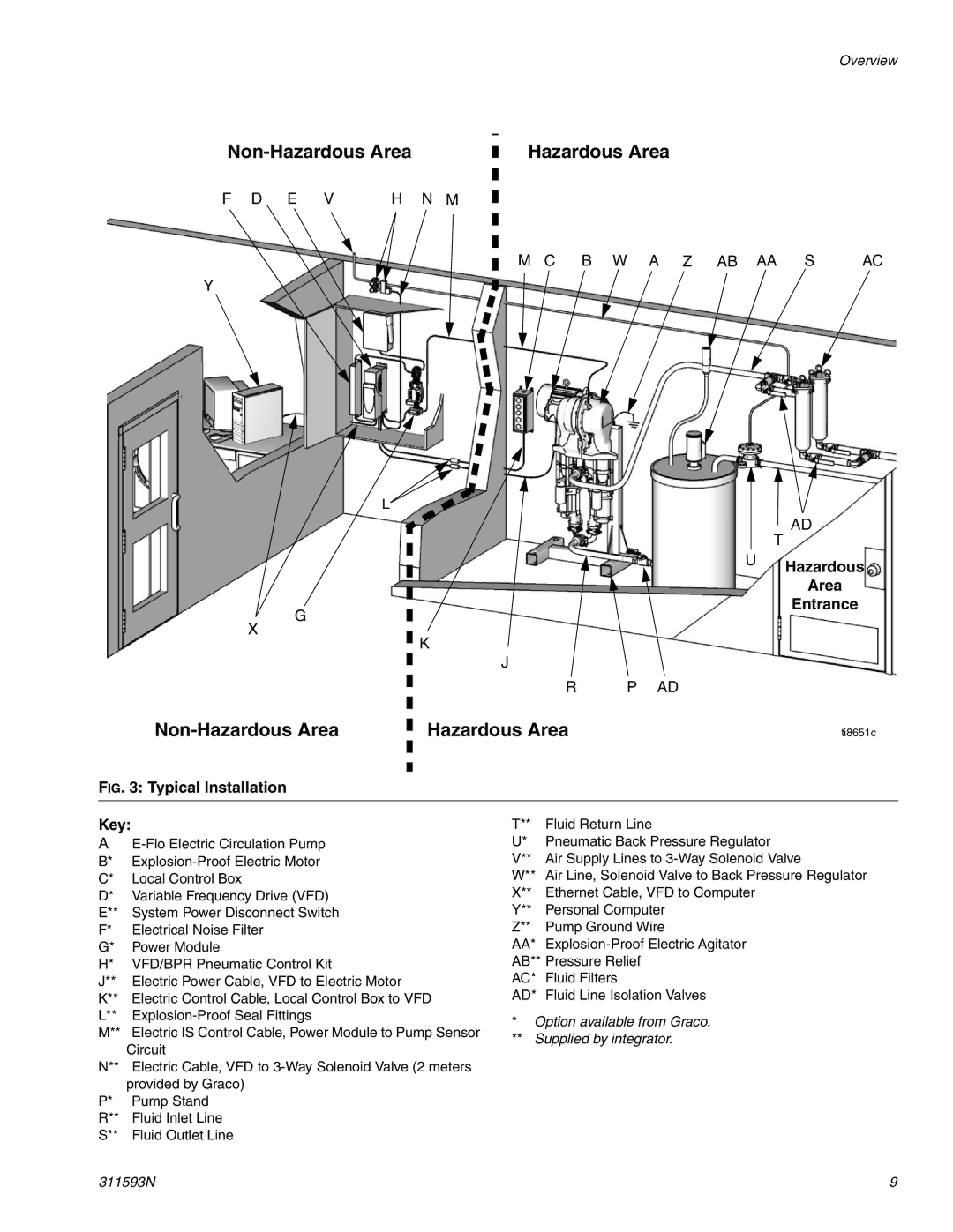
FIG. 3: Typical Installation
Key:
A
B* | |
C* | Local Control Box |
D* | Variable Frequency Drive (VFD) |
E** | System Power Disconnect Switch |
F* | Electrical Noise Filter |
G* | Power Module |
H* | VFD/BPR Pneumatic Control Kit |
J** | Electric Power Cable, VFD to Electric Motor |
K** | Electric Control Cable, Local Control Box to VFD |
L** | |
M** | Electric IS Control Cable, Power Module to Pump Sensor |
| Circuit |
N** | Electric Cable, VFD to |
| provided by Graco) |
P* | Pump Stand |
R** | Fluid Inlet Line |
S** | Fluid Outlet Line |
T** | Fluid Return Line |
U* | Pneumatic Back Pressure Regulator |
V** | Air Supply Lines to |
W** | Air Line, Solenoid Valve to Back Pressure Regulator |
X** | Ethernet Cable, VFD to Computer |
Y** | Personal Computer |
Z** | Pump Ground Wire |
AA* | |
AB** Pressure Relief | |
AC* | Fluid Filters |
AD* | Fluid Line Isolation Valves |
*Option available from Graco.
**Supplied by integrator.
311593N | 9 |