Manuals
/
Graco
/
Household Appliance
/
Heat Pump
Graco
Model 260409, Model 260408 Installation, Mounting Pump, Mounting Hose and Nozzle
Models:
Model 260410
Model 260409
Model 260408
1
4
14
14
Download
14 pages
728 b
1
2
3
4
5
6
7
8
Troubleshooting
Install
Parts list
Performance Chart
Warranty
Maintenance
Problem
Technical Data
Page 4
Image 4
Page 3
Page 5
Page 4
Image 4
Page 3
Page 5
Contents
Instructions - Parts List
GTP10 Herbicide Pump
311628C
Model 260408, 12 gpm 45 lpm, 115 VAC
Warnings
FIRE AND EXPLOSION HAZARD
ELECTRIC SHOCK HAZARD
PERSONAL PROTECTIVE EQUIPMENT
EQUIPMENT MISUSE HAZARD
BURN HAZARD
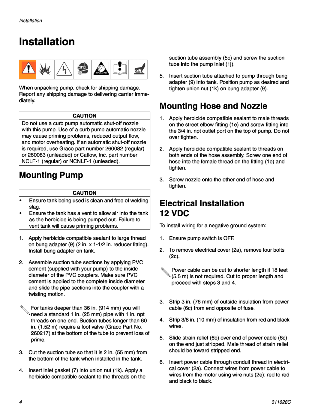
Installation
Electrical Installation 12 VDC
Mounting Pump
Mounting Hose and Nozzle
Electrical Installation 115 VAC
Priming Pump
Operation
Maintenance
Flushing Pump
Maintenance
311628C
Troubleshooting
Problem
Solution
Cause
Problem
Solution
Cause
Herbicide leaking in motor mount
Parts Drawing
Models 260410 and 260411, 12 VDC
Models 260408 and 260409, 115 VAC
260456
Parts List
Ref. No
Description
Ref. No
Technical Data
Performance Chart
54,%4402%3352%
772!4%
Technical Data
311628C
Graco Standard Warranty
Graco Information
Graco Headquarters Minneapolis
GRACO INC. P.O. BOX 1441 MINNEAPOLIS, MN
Top
Page
Image
Contents