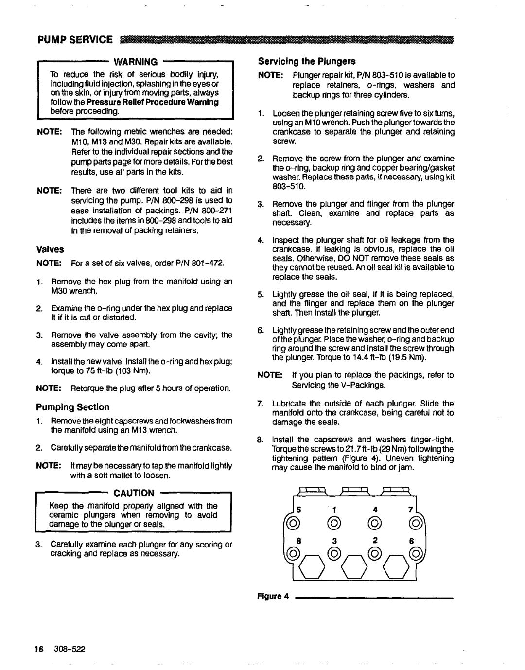
4040, 800-345, 308-522 specifications
Graco Inc. is a leading manufacturer known for its innovative fluid handling systems and equipment. Among its extensive product lineup, the model 4040,800-345,308-522 stands out due to its robust design and advanced technological features. Designed primarily for industrial applications, this model caters to various sectors, including manufacturing, construction, and automotive industries.One of the main features of the 4040,800-345,308-522 is its high-pressure capabilities. This model can handle a significant volume of fluid while maintaining an impressive control over pressure, ensuring efficient operation even in demanding environments. The durable construction material used in the pump's design contributes to its longevity and resilience against wear and tear.
Another notable characteristic of the Graco 4040 model is its precision fluid handling technology. The use of advanced engineering techniques allows for smooth operation and reduced downtime, which is vital for industries that rely on consistent performance. The pump is equipped with an intuitive control system, enabling users to easily manage and monitor operations in real-time.
The Graco 4040,800-345,308-522 additionally boasts an energy-efficient design. By optimizing fluid dynamics within the system, the model not only reduces operational costs but also minimizes its environmental impact. This focus on sustainability reflects Graco Inc.’s commitment to producing environmentally friendly products.
Moreover, the model features a user-friendly interface that simplifies setup and operation, making it accessible for technicians and workers alike. The inclusion of safety mechanisms enhances its usability, ensuring that even in high-pressure situations, the risk of accidents is minimized.
In terms of maintenance, the design facilitates easy access to components, allowing for quick servicing and minimal disruptions to workflow. This practicality can result in substantial time and cost savings over the equipment's lifespan.
Overall, the Graco Inc. 4040,800-345,308-522 exemplifies cutting-edge technology combined with practical features, making it a reliable choice for industries that demand high performance and efficiency. With its strong focus on durability, user-friendliness, and environmental responsibility, this model represents the high standards that Graco Inc. has set in the fluid handling equipment sector.

