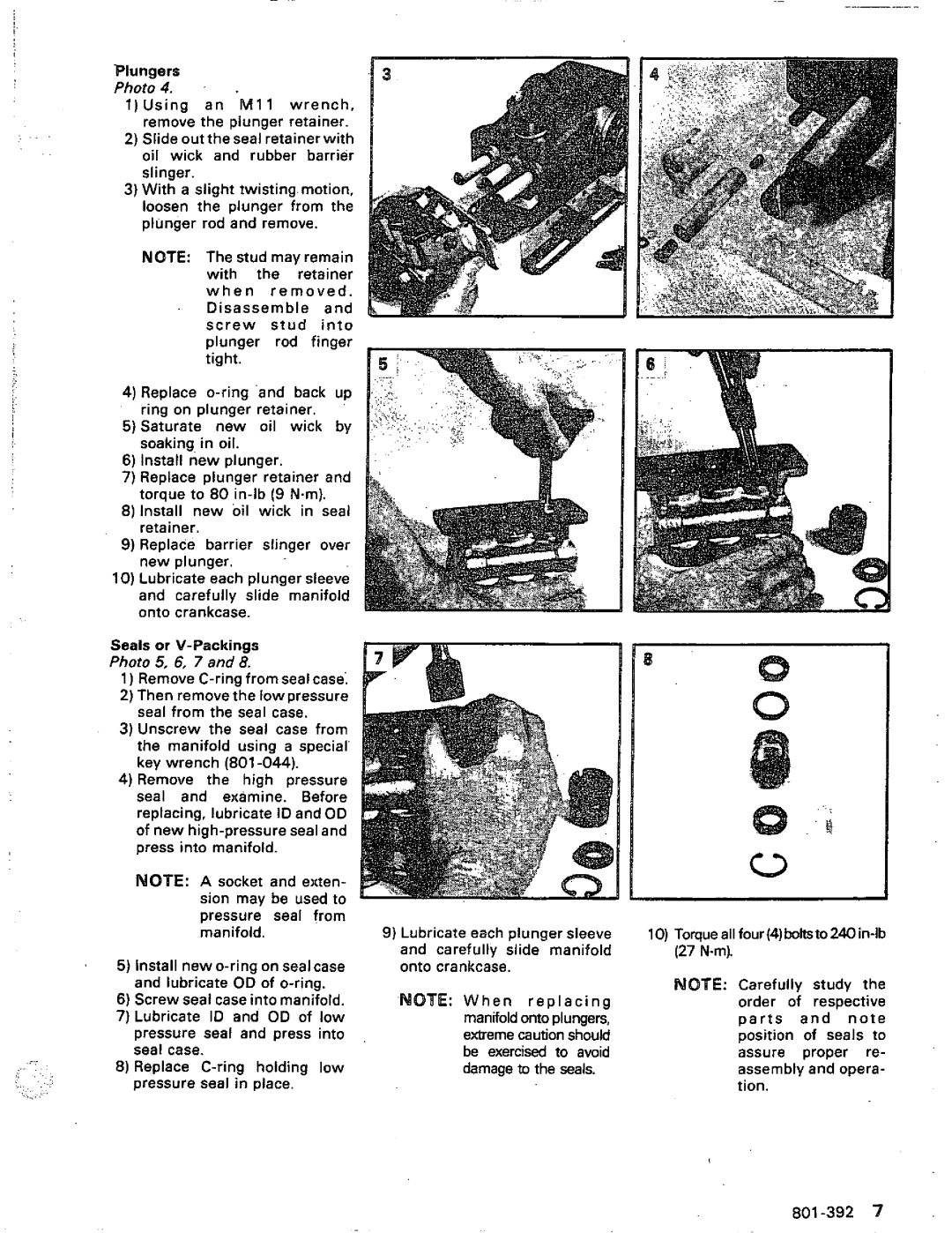
Plungers
Photo 4.
1 ) U s i n ga nM 1 1 wrench, remove the plunger retainer.
2)Slide out theseal retainer with
oilwick and rubberbarrier slinger.
3)With a slight twistingmotion, loosen the plungerfromthe plunger rod and remove.
NOTE: The stud may remain
withthe retainer w h e rne m o v e d . Disassembleand
s c r e ws t u idn t o plungerrodfinger tight.
4)Replace
5)Saturate newoil wick by soaking in oil.
6)Install new plunger.
7)Replace plunger retainer and torque to 80
8)Installnew oil wick in seal retainer.
9)Replace barrierslinger over
new plunger.
10)Lubricate each plunger sleeve andcarefullyslidemanifold onto crankcase.
Seals or
Photo 5, 6, 7 and 8.
1) Remove
2)Then removethe lowpressure seal from the seal case.
3)Unscrewthe seal case from themanifoldusing a special' key wrench
4)Remove thehighpressure
seal and examine. Before replacing, lubricateID and OD of new
MOTE: A socket andexten- sion maybeused to pressure seal from
k
,.
,.:
. ..,,., .
manifold.
5)Install
6)Screw seal case into manifold.
7)Lubricate ID and OD of low pressure seal and pressinto seal case.
8)Replace
9)Lubricate each plunger sleeve andcarefullyslidemanifold onto crankcase.
.NOTE: W h e nr e p l a c i n g manifoldonto plungers, ememe caution should be exercised to avoid damage to the seals.
10)
NOTE: Carefullystudythe order of respective p a r tasnndo t e position of sealsto assure proper re- assembly and opera- tion.