Grizzly G0747 and G0748 owner manual

Models: G0747 and G0748

1 80
Download 80 pages 42.76 Kb
Page 57
Image 57

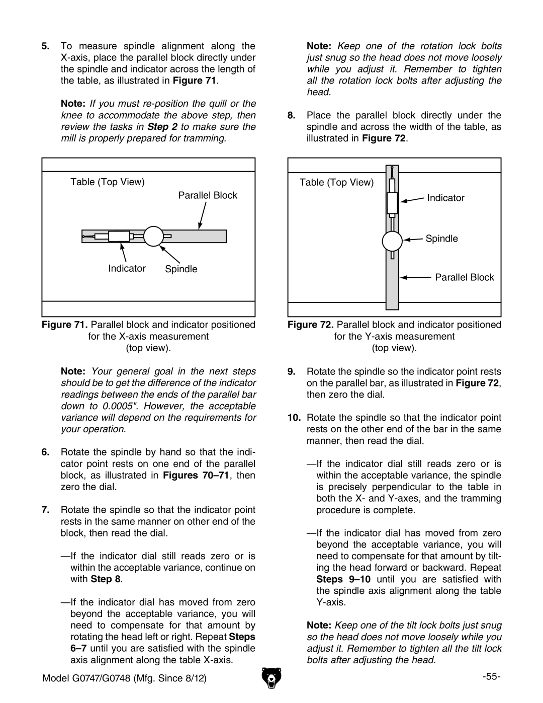
5.To measure spindle alignment along the X-axis, place the parallel block directly under the spindle and indicator across the length of the table, as illustrated in Figure 71.

Note: If you must re-position the quill or the knee to accommodate the above step, then review the tasks in Step 2 to make sure the mill is properly prepared for tramming.

Note: Keep one of the rotation lock bolts just snug so the head does not move loosely while you adjust it. Remember to tighten all the rotation lock bolts after adjusting the head.

8.place the parallel block directly under the spindle and across the width of the table, as illustrated in Figure 72.

Table (Top View)

Parallel Block

Indicator Spindle

Figure 71. Parallel block and indicator positioned

for the X-axis measurement

(top view).

Note: Your general goal in the next steps should be to get the difference of the indicator readings between the ends of the parallel bar down to 0.0005". However, the acceptable variance will depend on the requirements for your operation.

6.rotate the spindle by hand so that the indi- cator point rests on one end of the parallel block, as illustrated in Figures 70–71, then zero the dial.

7.rotate the spindle so that the indicator point rests in the same manner on other end of the block, then read the dial.

—if the indicator dial still reads zero or is within the acceptable variance, continue on with Step 8.

—if the indicator dial has moved from zero beyond the acceptable variance, you will need to compensate for that amount by rotating the head left or right. Repeat Steps 6–7until you are satisfied with the spindle axis alignment along the table X-axis.

Model G0747/G0748 (Mfg. Since 8/12)

Table (Top View)

Indicator

Spindle

Parallel Block

Figure 72. Parallel block and indicator positioned

for the Y-axis measurement

(top view).

9.rotate the spindle so the indicator point rests on the parallel bar, as illustrated in Figure 72, then zero the dial.

10.rotate the spindle so that the indicator point rests on the other end of the bar in the same manner, then read the dial.

—if the indicator dial still reads zero or is within the acceptable variance, the spindle is precisely perpendicular to the table in both the X- and Y-axes, and the tramming procedure is complete.

—if the indicator dial has moved from zero beyond the acceptable variance, you will need to compensate for that amount by tilt- ing the head forward or backward. Repeat Steps 9–10until you are satisfied with the spindle axis alignment along the table Y-axis.

Note: Keep one of the tilt lock bolts just snug so the head does not move loosely while you adjust it. Remember to tighten all the tilt lock bolts after adjusting the head.

-55-

Page 57
Image 57
Grizzly G0747 and G0748 owner manual

G0747 and G0748 specifications

The Grizzly G0747 and G0748 are advanced metal lathes designed for precision machining and versatility, catering to both amateur machinists and professional workshops. These machines stand out in the realm of metalworking equipment, thanks to their robust construction and innovative features.

One of the key attributes of the G0747 and G0748 is their solid cast iron construction, which provides excellent vibration dampening during operation. This enhances stability and precision, crucial for producing high-quality machined parts. Equipped with powerful motors, both models are capable of handling a wide range of materials, from aluminum to harder metals like steel.

The G0747 features a variable speed drive system, allowing users to adjust the spindle speed based on the project at hand. This flexibility is beneficial for tasks that require different cutting speeds, enabling machinists to optimize cutting performance and tool longevity. Its variable speed output ranges, alongside smooth torque delivery, make it ideal for intricate turning operations.

On the other hand, the G0748 includes an advanced digital readout (DRO) system. This feature provides real-time feedback on the machine's position and speed, significantly improving accuracy in measurements during machining tasks. The DRO system allows operators to set precise limits and keep track of their progress, essential for complex projects where exact dimensions are critical.

Both lathes are equipped with a user-friendly interface, making them accessible for beginners while still offering advanced functionalities that seasoned professionals appreciate. They include multiple tooling options, allowing for an expansive range of machining techniques including turning, threading, and drilling.

Moreover, the G0747 and G0748 come with a comprehensive assortment of accessories, such as different types of chucks and tool holders, which further extends their capabilities. The ease of changing tooling and quick setup times are significant advantages for shops aiming for efficiency and versatility in their operations.

In conclusion, the Grizzly G0747 and G0748 metal lathes are exemplary units that balance power, precision, and user-friendliness. Their advanced features, such as variable speed capabilities and digital readouts, equip machinists with the tools necessary to produce exceptional work. Whether for hobbyists or industrial applications, these lathes are built to meet a variety of machining needs with impressive performance and reliability.