5.Check for proper pulley alignment by plac- ing a straightedge on the outside edge of the upper pulley so that it overlaps the motor pulley. If the straightedge touches both pulleys evenly, the pulleys are aligned. If the straightedge does not touch both pul- leys evenly, the pulleys are not aligned. Loosen one or both of the pulley setscrews on their shafts and slide the pulleys toward alignment. Remember to retighten the setscrews when finished. See Figure 6.
Figure 6. Schematic of proper pulley alignment.
6.Adjust V-Belt tension by sliding the motor along the mounting slots. Proper tension is achieved when the belt can be deflected roughly 1/2" with moderate finger pressure.
7.Tighten the socket head cap screws securely. Recheck belt tension and pulley alignment.
Switch
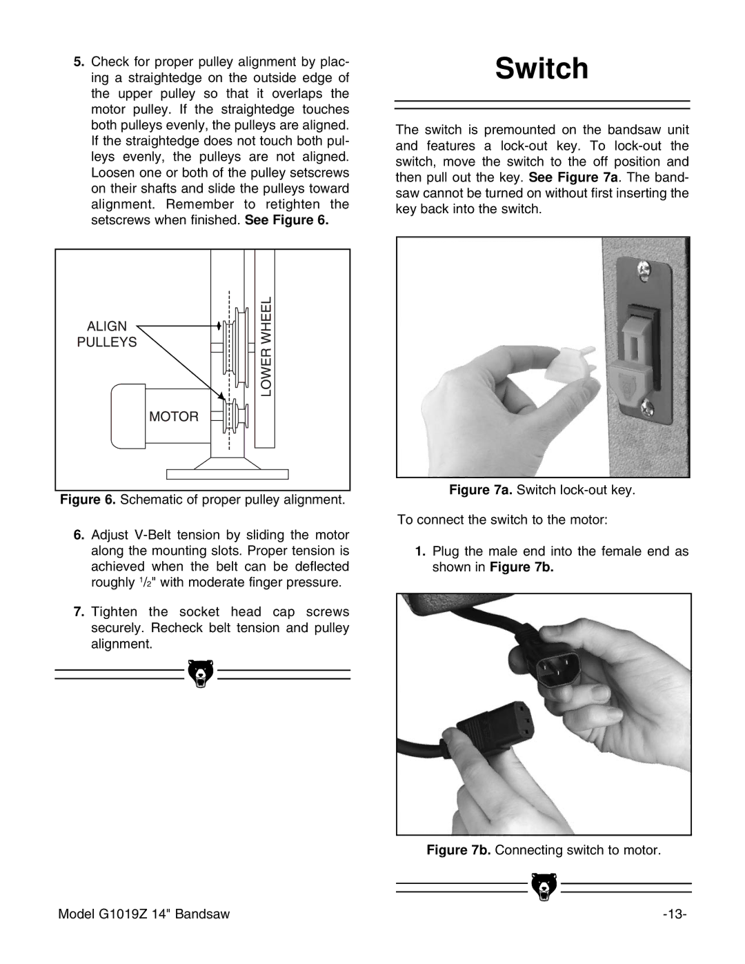
The switch is premounted on the bandsaw unit and features a
Figure 7a. Switch lock-out key.
To connect the switch to the motor:
1.Plug the male end into the female end as shown in Figure 7b.
Figure 7b. Connecting switch to motor.
Model G1019Z 14" Bandsaw |