6.Close the drain valve (Figure 5) to allow the tank to build up pressure.
Figure 5. Drain valve.
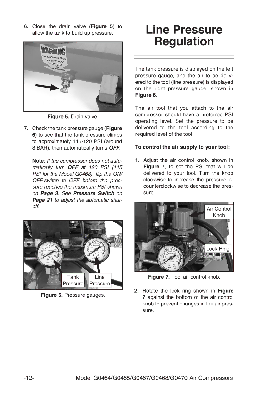
7.Check the tank pressure gauge (Figure 6) to see that the tank pressure climbs to approximately
Note: If the compressor does not auto- matically turn OFF at 120 PSI (115 PSI for the Model G0468), flip the ON/ OFF switch to OFF before the pres- sure reaches the maximum PSI shown on Page 3. See Pressure Switch on Page 21 to adjust the automatic shut- off.
Tank | Line |
Pressure | Pressure |
Figure 6. Pressure gauges. | |
Line Pressure Regulation
The tank pressure is displayed on the left pressure gauge, and the air to be deliv- ered to the tool (line pressure) is displayed on the right pressure gauge, shown in Figure 6.
The air tool that you attach to the air compressor should have a preferred PSI operating level. Set the pressure to be delivered to the tool according to the required level of the tool.
To control the air supply to your tool:
1.Adjust the air control knob, shown in Figure 7, to set the PSI that will be delivered to your tool. Turn the knob clockwise to increase the pressure or counterclockwise to decrease the pres- sure.
Air Control
Knob
Lock Ring
Figure 7. Tool air control knob.
2.Rotate the lock ring shown in Figure 7 against the bottom of the air control knob to prevent changes in the air pres- sure.
Model G0464/G0465/G0467/G0468/G0470 Air Compressors |