Assembly |
| Test Run |
|
|
|
|
|
|
The only assembly required is attaching the sup- port leg to the splitter assembly.
Components and Hardware Needed: | Qty |
Carriage Bolts | 5 |
Hex Nut | 5 |
To attach the support leg: |
|
1.Carefully lay the splitter on its side, with the wiring box facing up.
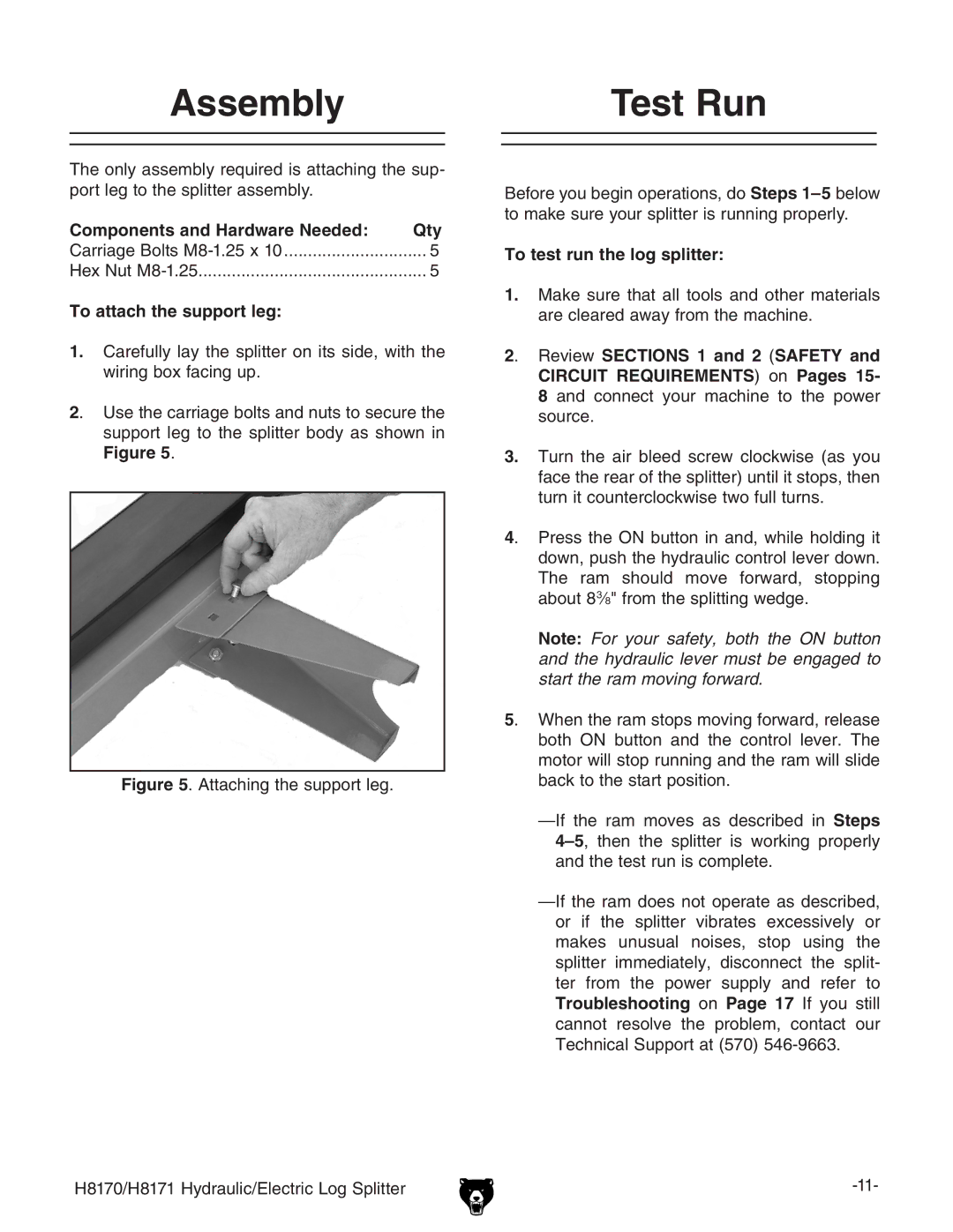
2. Use the carriage bolts and nuts to secure the support leg to the splitter body as shown in Figure 5.
Figure 5. Attaching the support leg.
Before you begin operations, do Steps 1–5 below to make sure your splitter is running properly.
To test run the log splitter:
1.Make sure that all tools and other materials are cleared away from the machine.
2. Review SECTIONS 1 and 2 (SAFETY and CIRCUIT REQUIREMENTS) on Pages 15- 8 and connect your machine to the power source.
3.Turn the air bleed screw clockwise (as you face the rear of the splitter) until it stops, then turn it counterclockwise two full turns.
4. Press the ON button in and, while holding it down, push the hydraulic control lever down. The ram should move forward, stopping about 8⁜3⁄8" from the splitting wedge.
Note: For your safety, both the ON button and the hydraulic lever must be engaged to start the ram moving forward.
5. When the ram stops moving forward, release both ON button and the control lever. The motor will stop running and the ram will slide back to the start position.
H8170/H8171 Hydraulic/Electric Log Splitter |
