Installation
1.DISCONNECT JOINTER FROM POWER!
2.Remove the jointer fence and cutterhead guard.
3.Remove the
4.Lower both beds to make enough room for the cutterhead to come out, as shown in
Figure 3.
Note: When lowering, make sure that the fence support does not come in contact with the cutterhead pulley.
Figure 3. Example of jointer disassembly Steps
5.Remove the nut and lock washer on the bear- ing block stud, as shown in Figure 4, and repeat on the other side.
Figure 4. Example of removing nut and lock
washer on bearing block stud.
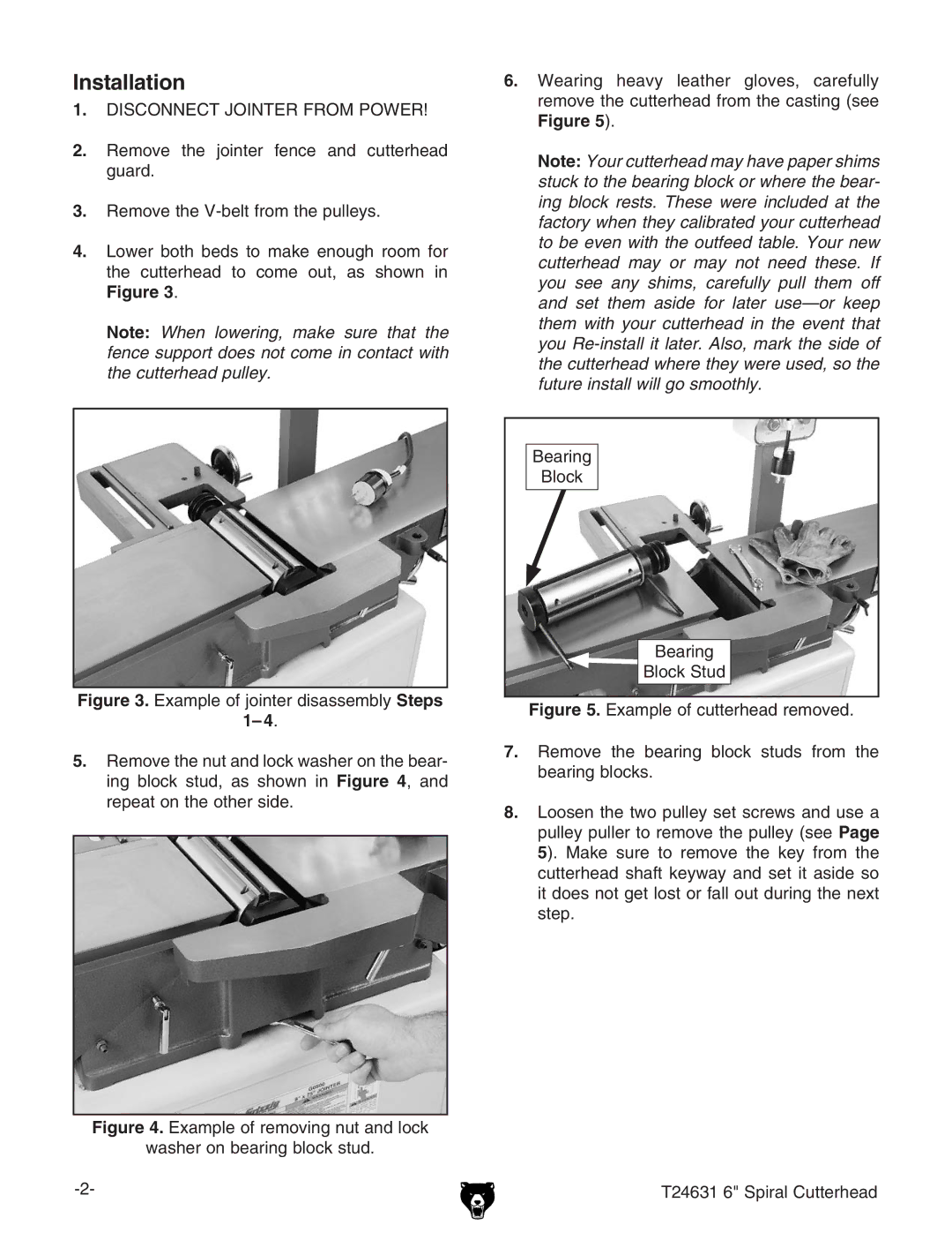
6.Wearing heavy leather gloves, carefully remove the cutterhead from the casting (see
Figure 5).
Note: Your cutterhead may have paper shims stuck to the bearing block or where the bear- ing block rests. These were included at the factory when they calibrated your cutterhead to be even with the outfeed table. Your new cutterhead may or may not need these. If you see any shims, carefully pull them off and set them aside for later
Bearing
Block
Bearing