19.Place a straightedge on the outfeed table so it extends over the cutterhead, and rotate the cutterhead pulley until one of the carbide inserts is at
Top Dead
Center
Figure 8. Cutterhead insert at top-dead-center.
Straightedge |
|
Outfeed | Infeed |
Figure 9. Setting outfeed table height.
When correctly set, the carbide insert will just touch the straightedge when the insert is at its highest point of rotation (Figure 9).
—If your outfeed table is correctly set, no adjustments are necessary.
—If the insert lifts the straightedge off the table or the table is below the straight- edge, adjust the outfeed table height with the handwheel until the straightedge just touches an insert at its highest point of rotation.
20.Lock the outfeed table, then Re-install the fence.
21.Install the cutterhead guard back over the cutterhead, making sure that the spring ten- sion in the guard is properly set so the guard springs back over the cutterhead when it is pulled back and released.
22.Re-adjust the infeed table.
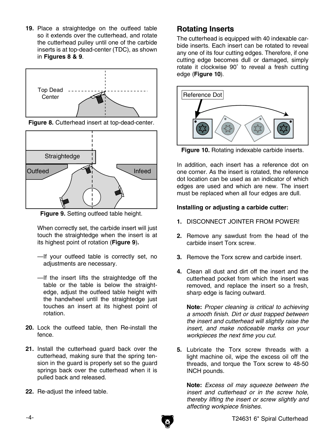
Rotating Inserts
The cutterhead is equipped with 40 indexable car- bide inserts. Each insert can be rotated to reveal any one of its four cutting edges. Therefore, if one cutting edge becomes dull or damaged, simply rotate it clockwise 90˚ to reveal a fresh cutting edge (Figure 10).
Reference Dot |
Figure 10. Rotating indexable carbide inserts.
In addition, each insert has a reference dot on one corner. As the insert is rotated, the reference dot location can be used as an indicator of which edges are used and which are new. The insert must be replaced when all four edges are dull.
Installing or adjusting a carbide cutter:
1.DISCONNECT JOINTER FROM POWER!
2.Remove any sawdust from the head of the carbide insert Torx screw.
3.Remove the Torx screw and carbide insert.
4.Clean all dust and dirt off the insert and the cutterhead pocket from which the insert was removed, and replace the insert so a fresh, sharp edge is facing outward.
Note: Proper cleaning is critical to achieving a smooth finish. Dirt or dust trapped between the insert and cutterhead will slightly raise the insert, and make noticeable marks on your workpieces the next time you cut.
5.Lubricate the Torx screw threads with a light machine oil, wipe the excess oil off the threads, and torque the Torx screw to
Note: Excess oil may squeeze between the insert and cutterhead or in the screw hole, thereby lifting the insert or screw slightly and affecting workpiece finishes.
T24631 6" Spiral Cutterhead