Front Panel and Rear Panel Illustration
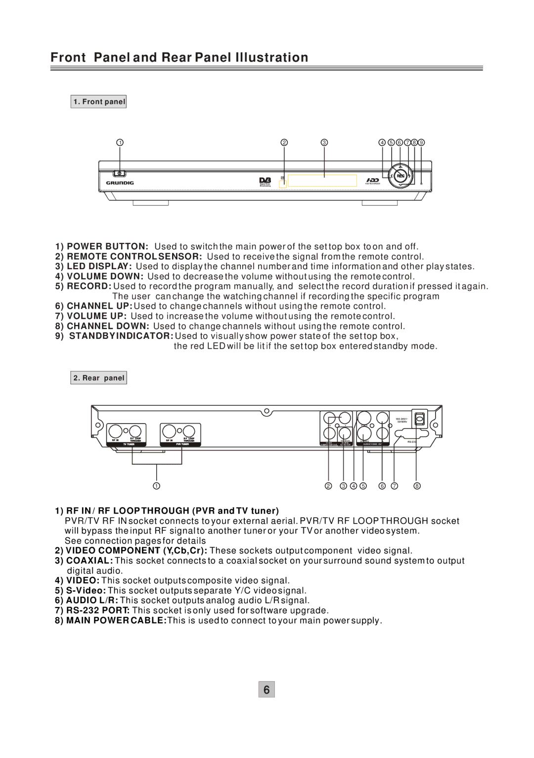
1. Front panel
1 | 2 | 3 | 4 | 5 | 6 | 7 | 8 | 9 |
1)POWER BUTTON: Used to switch the main power of the set top box to on and off.
2)REMOTE CONTROL SENSOR: Used to receive the signal from the remote control.
3)LED DISPLAY: Used to display the channel number and time information and other play states.
4)VOLUME DOWN: Used to decrease the volume without using the remote control.
5)RECORD: Used to record the program manually, and select the record duration if pressed it again. The user can change the watching channel if recording the specific program
6)CHANNEL UP: Used to change channels without using the remote control.
7)VOLUME UP: Used to increase the volume without using the remote control.
8)CHANNEL DOWN: Used to change channels without using the remote control.
9)STANDBY INDICATOR: Used to visually show power state of the set top box,
the red LED will be lit if the set top box entered standby mode.
2. Rear panel
|
|
|
|
|
|
|
|
|
| ||
|
|
|
|
|
|
|
|
|
|
| 50/60Hz |
|
|
|
|
| Cb | Y |
| VIDEO | L |
|
|
R F IN | R F | LOOP | R F IN | R F LOOP | Cr | COAXIAL |
|
|
|
|
|
THROUGH | THROUGH |
| R |
| |||||||
| TV TUNER |
|
| PVR TUNER | VIDEO | DIGITAL |
| AUDIO/VIDEO OUT |
| ||
|
|
| COMPONENT OUT | AUDIO OUT |
|
|
| ||||
|
| 1 |
|
| 2 | 3 | 4 | 5 | 6 | 7 | 8 |
1) RF IN / RF LOOP THROUGH (PVR and TV tuner)
PVR/TV RF IN socket connects to your external aerial. PVR/TV RF LOOP THROUGH socket will bypass the input RF signal to another tuner or your TV or another video system.
See connection pages for details
2)VIDEO COMPONENT (Y,Cb,Cr): These sockets output component video signal.
3)COAXIAL: This socket connects to a coaxial socket on your surround sound system to output digital audio.
4)VIDEO: This socket outputs composite video signal.
5)
6)AUDIO L/R: This socket outputs analog audio L/R signal.
7)
8)MAIN POWER CABLE:This is used to connect to your main power supply.
6