CAUTION
HYDROGEN GAS can be produced in a hot water system served by this heater that has not been used for a long period of time (generally two weeks or more). HYDROGEN GAS IS EXTREMELY FLAMMABLE. To reduce the risk of injury under these conditions, it is recommended that the hot water faucet be opened for several minutes at the kitchen sink before using any electrical appliance connected to the hot water system. If hydrogen is present, there will probably be an unusual sound, such as air escaping through the pipe as the water begins to flow.
THERE SHOULD BE NO SMOKING, OR OPEN FLAME NEAR THE FAUCET AT THE TIME THAT IT IS OPEN.
INSTALLATION INSTRUCTIONS Location and Clearances
Location selected should be as close to the stack or chimney as practical and as centralized with the piping system as possible. The heater should be located in an area not subject to freezing temperatures.
Locate near a floor drain and in an area where leakage of the tank or water piping will not result in damaging adjacent areas or lower floors of the structure. Where such a location is not available, a suitable drain pan, not restricting combustion air flow, must be installed under the water heater. This pan shall be 1½“ (40 mm) deep and a diameter that is a minimum of 2” (50 mm) greater than the diameter of the water heater. A suitable pipe properly connected to an adjacent floor drain shall be provided.
GSW CANNOT BE HELD RESPONSIBLE for damage caused by water from the water heater, pressure relief valve, or related fittings where adequate provisions to drain such water has not been made.
Locate the water heater such that all controls are easily accessible. We recommend that 24” (0.6 m) in front of the heater and 34”(0.9m) above be maintained for serviceability. Ensure that the water heater is level.
Minimum clearances between the heater and combustible materials are: 1”(25mm) sides and rear; 4”(100mm) at the front; open on an alcove; 8”(200mm) from the top of the water heater and the flue 6”(150mm), except for certain models will have different wall clearances as shown in Table (1) below. This heater may be installed in a closet or alcove and is certified for operation on a combustible floor.
MODEL# | 6058 | 602/60E | 5063T | 4060T | |
FRONT | 5"/13cm | 5"/13cm | 5"/13cm | 5"/13cm | 5"/13cm |
CLEARANCE |
TABLE 1
FIGURE 1
WARNING
Do not install directly on carpet. Instead, place the water heater on a metal or wood panel extending a minimum of 3” (75 mm) from all sides. In alcoves or closets, cover the carpet completely. Ensure that this panel is capable of supporting the weight of this heater when filled with water.
FAILURE TO PROPERLY INSTALL THIS HEATER MAY RESULT IN A FIRE HAZARD.
HOT OUTLET |
|
|
|
|
|
|
|
|
|
|
|
|
|
|
|
|
|
|
|
|
|
|
|
|
|
|
|
| COLD INLET | ||||||||||
|
| “G” |
|
|
|
|
|
|
|
|
|
|
|
|
|
|
|
|
|
|
|
|
|
|
|
| |||||||||||||
3/4” NPT |
|
|
|
|
|
|
|
|
|
|
|
|
|
|
|
|
|
|
|
|
|
|
|
|
|
|
|
|
| 3/4” NPT | |||||||||
|
|
|
|
|
|
|
|
|
|
|
|
|
|
|
|
|
|
|
|
|
|
|
|
|
|
|
|
|
|
|
|
|
|
|
|
|
|
|
|
|
|
|
|
|
|
|
|
|
|
|
|
|
|
|
|
|
|
|
|
|
|
|
|
|
|
|
|
|
|
|
|
|
|
|
|
|
|
|
|
|
|
|
|
|
|
|
|
|
|
|
|
|
|
|
|
|
|
|
|
|
|
|
|
|
|
|
|
|
|
|
|
|
|
|
|
|
|
| |
|
|
|
|
|
|
|
|
|
|
|
|
|
|
|
|
|
|
|
|
|
|
|
|
|
|
|
|
|
|
|
|
|
|
|
| ||||
|
|
|
|
|
|
|
|
|
|
|
|
|
| “H” |
|
|
|
|
|
|
|
|
|
|
|
|
|
|
|
|
| ||||||||
|
|
|
|
|
|
|
|
|
|
|
|
|
|
|
|
|
|
|
|
|
|
|
|
|
| ||||||||||||||
|
|
|
|
|
|
|
|
|
|
|
|
|
|
|
|
|
|
|
|
|
|
|
|
|
|
|
|
|
|
|
|
|
|
|
| ||||
|
|
|
|
|
|
|
|
|
|
|
|
|
|
|
|
|
|
|
|
|
|
|
| T&P |
|
|
|
|
|
|
|
|
|
|
| ||||
|
|
|
|
|
|
|
|
|
|
|
|
|
|
|
|
|
|
| VALVE |
|
|
|
|
|
|
|
|
|
|
| |||||||||
|
|
|
|
|
|
|
|
|
|
|
|
|
|
|
|
|
|
|
|
|
|
|
|
|
|
|
|
|
|
|
| ||||||||
|
|
|
|
|
|
|
|
|
|
|
|
|
|
|
|
|
|
|
|
|
|
|
|
|
|
|
|
|
|
|
|
|
|
|
|
|
|
|
|
|
|
|
|
|
|
|
|
|
|
|
|
|
|
|
|
| “A” |
|
|
|
|
|
|
|
|
|
|
| |||||||||||
| “F | ” |
|
|
|
|
|
|
|
|
|
|
|
|
|
|
|
|
|
|
|
| |||||||||||||||||
|
|
|
|
|
|
|
|
|
|
|
|
|
|
|
|
| “E” | ||||||||||||||||||||||
|
|
|
|
|
|
|
|
|
|
|
|
|
|
|
|
|
|
|
|
|
|
|
|
|
|
|
|
|
|
|
|
|
|
|
|
|
|
|
|
|
|
|
|
|
|
|
|
|
|
|
|
|
|
|
|
|
|
|
|
|
|
|
|
|
|
|
|
|
|
|
|
|
|
|
|
|
|
|
|
|
|
|
|
|
|
|
|
|
|
|
|
|
|
|
|
|
|
|
|
|
|
| |||||||||||||||||
|
|
|
|
|
|
|
|
| GAS INLET |
|
|
|
|
|
|
|
|
|
| ||||||||||||||||||||
|
|
|
|
|
|
|
|
|
|
|
|
|
|
|
|
|
| ||||||||||||||||||||||
|
|
|
|
|
|
|
|
| 1/2” NPT |
|
|
|
|
| “D” | ||||||||||||||||||||||||
|
|
|
|
|
|
|
|
|
|
|
|
|
|
|
|
|
|
|
|
|
|
|
|
|
|
|
|
|
|
|
|
|
|
| |||||
| DRAIN |
“C” | VALVE |
| “B” |
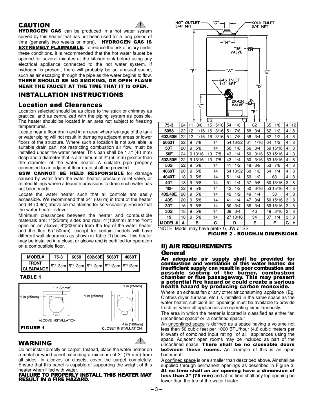
24 | 11 | 3/8 | 15 | 5/16 | 54 | 1/8 |
| 62 | 65 | 1/8 | 4 | 12 | |
6058 | 22 | 12 | 1/16 | 16 | 3/16 | 51 | 7/8 | 58 | 3/4 | 62 | 1/2 | 4 | 8 |
602/60E | 22 | 12 | 1/16 | 16 | 3/16 | 51 | 7/8 | 58 | 3/4 | 62 | 1/2 | 4 | 8 |
5063T | 22 | 9 | 7/8 |
| 14 | 54 13/32 | 61 | 1/16 | 64 | 1/2 | 4 | 8 | |
50T | 20 | 9 | 5/8 |
| 14 | 50 | 1/8 | 56 | 3/4 | 59 | 15/16 | 4 | 8 |
50F | 24 | 9 13/16 | 13 | 7/8 | 43 | 1/4 | 50 | 3/16 | 53 | 15/16 | 4 | 8 | |
502/50E | 22 | 9 13/16 | 13 | 7/8 | 43 | 1/4 | 50 | 3/16 | 53 | 15/16 | 4 | 8 | |
50S | 22 | 9 | 5/8 |
| 14 | 41 | 1/2 | 48 | 3/8 | 53 | 7/8 | 4 | 8 |
4060T | 20 | 9 | 5/8 |
| 14 | 54 13/32 | 60 | 1/2 | 64 | 1/4 | 4 | 8 | |
4040T | 18 | 9 | 5/8 |
| 14 | 51 | 1/4 | 59 | 1/2 |
| 63 | 4 | 8 |
40T | 18 | 9 | 5/8 |
| 14 | 51 | 1/4 | 57 | 5/8 | 60 | 13/16 | 3 | 8 |
40F | 22 | 9 | 5/8 |
| 14 | 42 | 1/2 | 50 | 3/16 | 53 | 15/16 | 4 | 8 |
402/40E | 20 | 9 | 5/8 |
| 14 | 42 | 1/2 | 49 | 1/4 |
| 53 | 4 | 8 |
40S | 20 | 9 | 5/8 |
| 14 | 41 | 1/4 | 47 | 3/4 | 50 | 15/16 | 3 | 8 |
30T | 16 | 9 | 5/8 |
| 14 | 50 | 3/4 | 56 | 3/4 | 59 | 15/16 | 3 | 8 |
30S | 18 | 9 | 5/8 |
| 14 | 39 | 3/4 |
| 46 | 49 | 3/16 | 3 | 8 |
19 | 18 | 9 | 5/8 |
| 14 | 27 13/16 |
| 34 | 37 | 1/4 | 3 | 8 | |
MODEL # | A |
| B |
| C |
| D |
| E |
| F | G | H |
*NOTE: Model may have prefix G, JW or SS
FIGURE 2 - ROUGH-IN DIMENSIONS
II)AIR REQUIREMENTS General
An adequate air supply shall be provided for combustion and ventilation of this water heater. An insufficient supply can result in poor combustion and possible sooting of the burner, combustion chamber or flue passageway. This may present a potential fire hazard or could create a serious health hazard by producing carbon monoxide.
Where an exhaust fan or any other air consuming appliance (Eg. Clothes dryer, furnace, etc.) is installed in the same space as the water heater, sufficient air openings must be available to provide fresh air when all appliances are operating simultaneously.
The area in which the heater is located is classified as either “an unconfined space” or “a confined space.”
An unconfined space is defined as a space having a volume not less than 50 cubic feet per 1000 BTU/hour (4.8 cubic meters per kilowatt) of combined input rating of all appliances using the space. Adjacent open rooms may be included as part of the unconfined space. There shall be no closeable doors between these rooms. An example of this is an open basement.
A confined space is one smaller than described above. Air shall be supplied through permanent openings as described in Figure 3.
At no time shall an air opening have a dimension of less than 3” (75 mm) and at no time shall any top opening be lower than the top of the water heater.
– 3 –