FIGURE 4 |
III) GAS CONNECTIONS
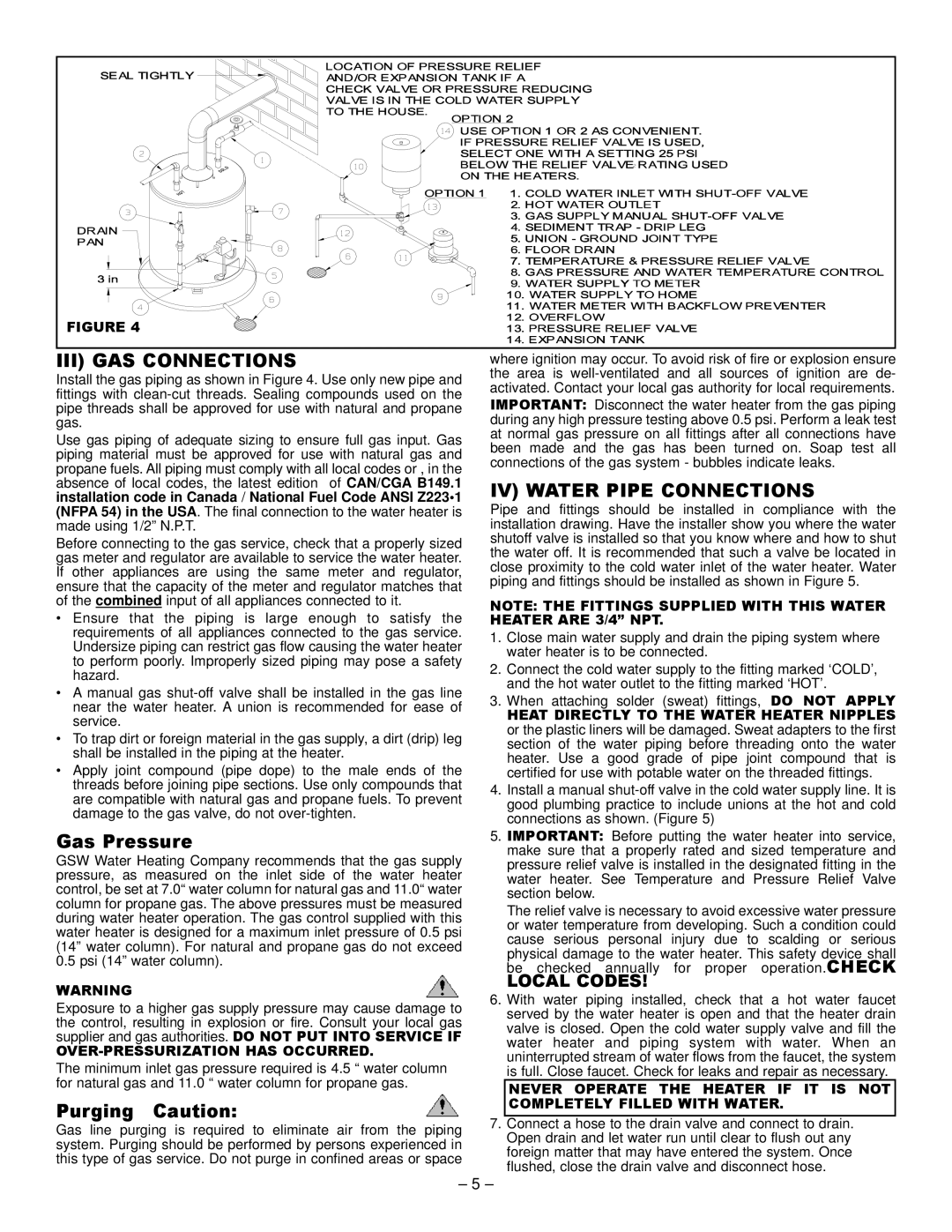
Install the gas piping as shown in Figure 4. Use only new pipe and fittings with
Use gas piping of adequate sizing to ensure full gas input. Gas piping material must be approved for use with natural gas and propane fuels. All piping must comply with all local codes or , in the absence of local codes, the latest edition of CAN/CGA B149.1 installation code in Canada / National Fuel Code ANSI Z223•1 (NFPA 54) in the USA. The final connection to the water heater is made using 1/2” N.P.T.
Before connecting to the gas service, check that a properly sized gas meter and regulator are available to service the water heater. If other appliances are using the same meter and regulator, ensure that the capacity of the meter and regulator matches that of the combined input of all appliances connected to it.
•Ensure that the piping is large enough to satisfy the requirements of all appliances connected to the gas service. Undersize piping can restrict gas flow causing the water heater to perform poorly. Improperly sized piping may pose a safety hazard.
•A manual gas
•To trap dirt or foreign material in the gas supply, a dirt (drip) leg shall be installed in the piping at the heater.
•Apply joint compound (pipe dope) to the male ends of the threads before joining pipe sections. Use only compounds that are compatible with natural gas and propane fuels. To prevent damage to the gas valve, do not
where ignition may occur. To avoid risk of fire or explosion ensure the area is
IMPORTANT: Disconnect the water heater from the gas piping during any high pressure testing above 0.5 psi. Perform a leak test at normal gas pressure on all fittings after all connections have been made and the gas has been turned on. Soap test all connections of the gas system - bubbles indicate leaks.
IV) WATER PIPE CONNECTIONS
Pipe and fittings should be installed in compliance with the installation drawing. Have the installer show you where the water shutoff valve is installed so that you know where and how to shut the water off. It is recommended that such a valve be located in close proximity to the cold water inlet of the water heater. Water piping and fittings should be installed as shown in Figure 5.
NOTE: THE FITTINGS SUPPLIED WITH THIS WATER HEATER ARE 3/4” NPT.
1.Close main water supply and drain the piping system where water heater is to be connected.
2.Connect the cold water supply to the fitting marked ‘COLD’, and the hot water outlet to the fitting marked ‘HOT’.
3.When attaching solder (sweat) fittings, DO NOT APPLY
HEAT DIRECTLY TO THE WATER HEATER NIPPLES or the plastic liners will be damaged. Sweat adapters to the first section of the water piping before threading onto the water heater. Use a good grade of pipe joint compound that is certified for use with potable water on the threaded fittings.
4.Install a manual
Gas Pressure | 5. IMPORTANT: Before putting the water heater into service, | ||
GSW Water Heating Company recommends that the gas supply |
| make sure that a properly rated and sized temperature and | |
| pressure relief valve is installed in the designated fitting in the | ||
pressure, as measured on the inlet side of the water heater |
| water heater. See Temperature and Pressure Relief Valve | |
control, be set at 7.0“ water column for natural gas and 11.0“ water |
| section below. | |
column for propane gas. The above pressures must be measured |
| The relief valve is necessary to avoid excessive water pressure | |
during water heater operation. The gas control supplied with this |
| ||
| or water temperature from developing. Such a condition could | ||
water heater is designed for a maximum inlet pressure of 0.5 psi |
| ||
| cause serious personal injury due to scalding or serious | ||
(14” water column). For natural and propane gas do not exceed |
| ||
| physical damage to the water heater. This safety device shall | ||
0.5 psi (14” water column). |
| ||
| be checked annually for proper operation.CHECK | ||
|
| ||
WARNING |
| LOCAL CODES! | |
6. With water piping installed, check that a hot water faucet | |||
Exposure to a higher gas supply pressure may cause damage to | |||
| served by the water heater is open and that the heater drain | ||
the control, resulting in explosion or fire. Consult your local gas |
| ||
| valve is closed. Open the cold water supply valve and fill the | ||
supplier and gas authorities. DO NOT PUT INTO SERVICE IF |
| ||
| water heater and piping system with water. When an | ||
|
| ||
| uninterrupted stream of water flows from the faucet, the system | ||
The minimum inlet gas pressure required is 4.5 “ water column |
| ||
| is full. Close faucet. Check for leaks and repair as necessary. | ||
for natural gas and 11.0 “ water column for propane gas. |
|
| |
| NEVER OPERATE THE HEATER IF IT IS NOT | ||
Purging Caution: |
| COMPLETELY FILLED WITH WATER. | |
|
| ||
7. Connect a hose to the drain valve and connect to drain. | |||
Gas line purging is required to eliminate air from the piping | |||
| Open drain and let water run until clear to flush out any | ||
system. Purging should be performed by persons experienced in |
| ||
| foreign matter that may have entered the system. Once | ||
this type of gas service. Do not purge in confined areas or space |
| ||
| flushed, close the drain valve and disconnect hose. | ||
|
| ||
– 5 –