>1”>1”

WALL

10”

(REF)

68 MINIMUM

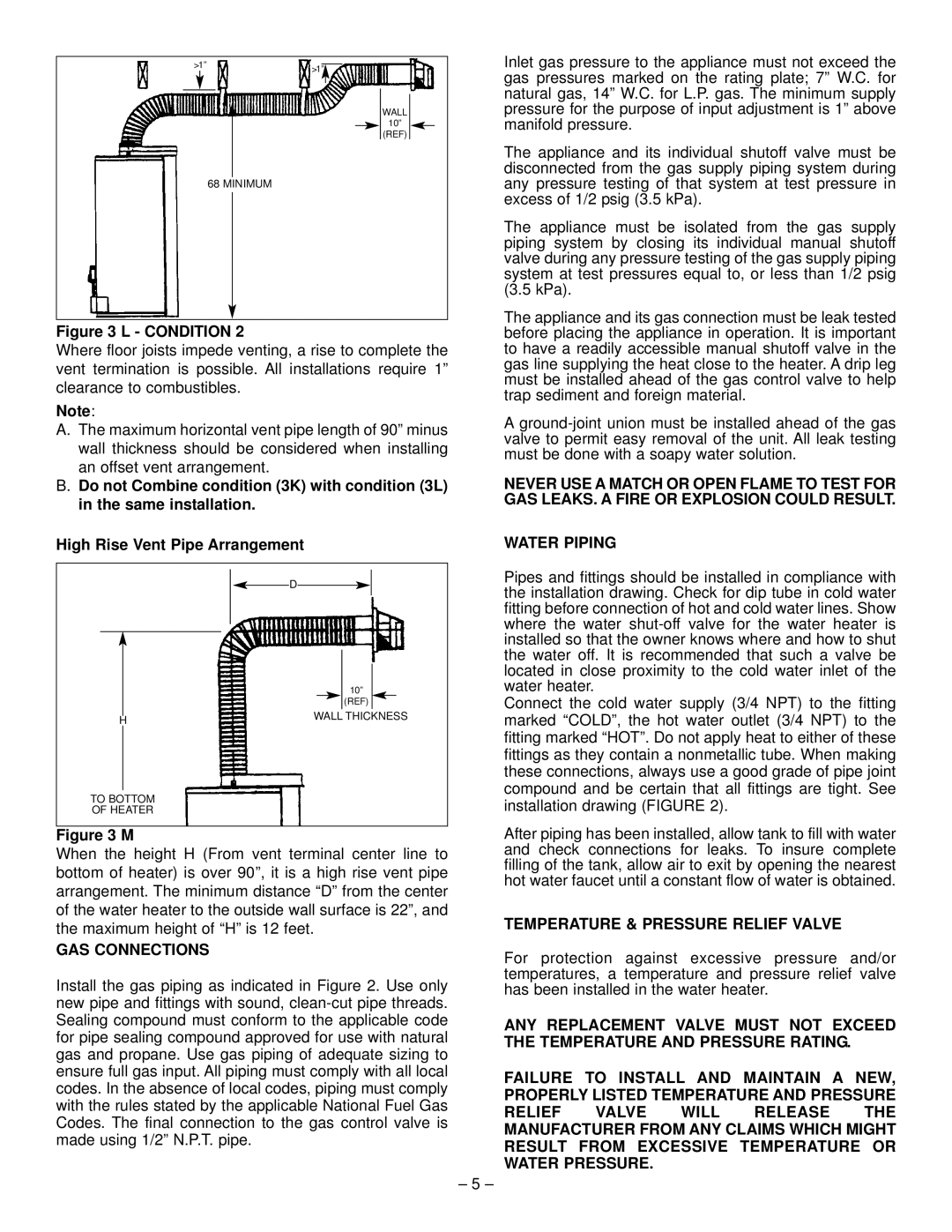
Figure 3 L - CONDITION 2

Where floor joists impede venting, a rise to complete the vent termination is possible. All installations require 1” clearance to combustibles.

Note:

A.The maximum horizontal vent pipe length of 90” minus wall thickness should be considered when installing an offset vent arrangement.

B.Do not Combine condition (3K) with condition (3L) in the same installation.

High Rise Vent Pipe Arrangement

Inlet gas pressure to the appliance must not exceed the gas pressures marked on the rating plate; 7” W.C. for natural gas, 14” W.C. for L.P. gas. The minimum supply pressure for the purpose of input adjustment is 1” above manifold pressure.

The appliance and its individual shutoff valve must be disconnected from the gas supply piping system during any pressure testing of that system at test pressure in excess of 1/2 psig (3.5 kPa).

The appliance must be isolated from the gas supply piping system by closing its individual manual shutoff valve during any pressure testing of the gas supply piping system at test pressures equal to, or less than 1/2 psig (3.5 kPa).

The appliance and its gas connection must be leak tested before placing the appliance in operation. It is important to have a readily accessible manual shutoff valve in the gas line supplying the heat close to the heater. A drip leg must be installed ahead of the gas control valve to help trap sediment and foreign material.

A ground-joint union must be installed ahead of the gas valve to permit easy removal of the unit. All leak testing must be done with a soapy water solution.

NEVER USE A MATCH OR OPEN FLAME TO TEST FOR GAS LEAKS. A FIRE OR EXPLOSION COULD RESULT.

WATER PIPING

D


10”


(REF)


WALL THICKNESS

H


TO BOTTOM

OF HEATER

Figure 3 M

When the height H (From vent terminal center line to bottom of heater) is over 90”, it is a high rise vent pipe arrangement. The minimum distance “D” from the center of the water heater to the outside wall surface is 22”, and the maximum height of “H” is 12 feet.

GAS CONNECTIONS

Install the gas piping as indicated in Figure 2. Use only new pipe and fittings with sound, clean-cut pipe threads. Sealing compound must conform to the applicable code for pipe sealing compound approved for use with natural gas and propane. Use gas piping of adequate sizing to ensure full gas input. All piping must comply with all local codes. In the absence of local codes, piping must comply with the rules stated by the applicable National Fuel Gas Codes. The final connection to the gas control valve is made using 1/2” N.P.T. pipe.

– 5 –

Pipes and fittings should be installed in compliance with the installation drawing. Check for dip tube in cold water fitting before connection of hot and cold water lines. Show where the water shut-off valve for the water heater is installed so that the owner knows where and how to shut the water off. It is recommended that such a valve be located in close proximity to the cold water inlet of the water heater.

Connect the cold water supply (3/4 NPT) to the fitting marked “COLD”, the hot water outlet (3/4 NPT) to the fitting marked “HOT”. Do not apply heat to either of these fittings as they contain a nonmetallic tube. When making these connections, always use a good grade of pipe joint compound and be certain that all fittings are tight. See installation drawing (FIGURE 2).

After piping has been installed, allow tank to fill with water and check connections for leaks. To insure complete filling of the tank, allow air to exit by opening the nearest hot water faucet until a constant flow of water is obtained.

TEMPERATURE & PRESSURE RELIEF VALVE

For protection against excessive pressure and/or temperatures, a temperature and pressure relief valve has been installed in the water heater.

ANY REPLACEMENT VALVE MUST NOT EXCEED THE TEMPERATURE AND PRESSURE RATING.

FAILURE TO INSTALL AND MAINTAIN A NEW, PROPERLY LISTED TEMPERATURE AND PRESSURE

RELIEF VALVE WILL RELEASE THE MANUFACTURER FROM ANY CLAIMS WHICH MIGHT RESULT FROM EXCESSIVE TEMPERATURE OR WATER PRESSURE.

Page 6
Image 6
GSW PART NO.70999 REV.G (03-12) operating instructions GAS Connections, Temperature & Pressure Relief Valve

PART NO.70999 REV.G (03-12) specifications

The GSW PART NO. 70999 REV.G (03-12) is an exemplary product designed for high-performance application in various industrial settings. This part stands out not only for its robust construction but also for its advanced technological features, which cater to the evolving demands of modern industry.

One of the main characteristics of the GSW 70999 REV.G is its durable design, engineered to withstand challenging operational conditions. The materials used in its construction are specifically chosen for their strength and resistance to wear and corrosion, ensuring longevity and reliability in performance. This makes the component an ideal choice for applications that require consistent and dependable operation over extended periods.

In terms of technology, the GSW 70999 REV.G incorporates cutting-edge manufacturing processes that enhance its precision and functionality. The advanced machining techniques employed ensure tight tolerances and superior fit, which contribute to improved efficiency in machinery operation. This precision is particularly critical in high-speed applications, where even minor discrepancies can lead to significant performance issues.

Another key feature of the GSW 70999 REV.G is its adaptability. The part is designed with versatility in mind, allowing it to be integrated seamlessly into a variety of systems and equipment. This adaptability minimizes downtime during installation and maintenance, as users can easily incorporate the part into their existing configurations without extensive modifications.

The GSW 70999 REV.G also benefits from innovative design aspects such as ergonomic considerations, which aim to simplify handling and improve user experience. The thoughtful layout and accessibility of the component facilitate easier maintenance procedures, ultimately reducing operational costs and maximizing productivity for users.

Furthermore, GSW emphasizes sustainability in its product design and manufacturing processes. The materials are selected not only for their performance characteristics but also for their environmental impact, aligning with the industry's growing focus on sustainability and responsible sourcing.

In summary, the GSW PART NO. 70999 REV.G (03-12) is a crucial component characterized by its durability, precision, adaptability, and commitment to sustainability. It serves as an integral part in various industrial applications, promoting efficiency and reliability while catering to the increasing demands of modern technological advancement. Whether in high-speed settings or more moderate environments, this part exemplifies quality and innovation in industrial design.