Specially For Direct Vent Water Heater:

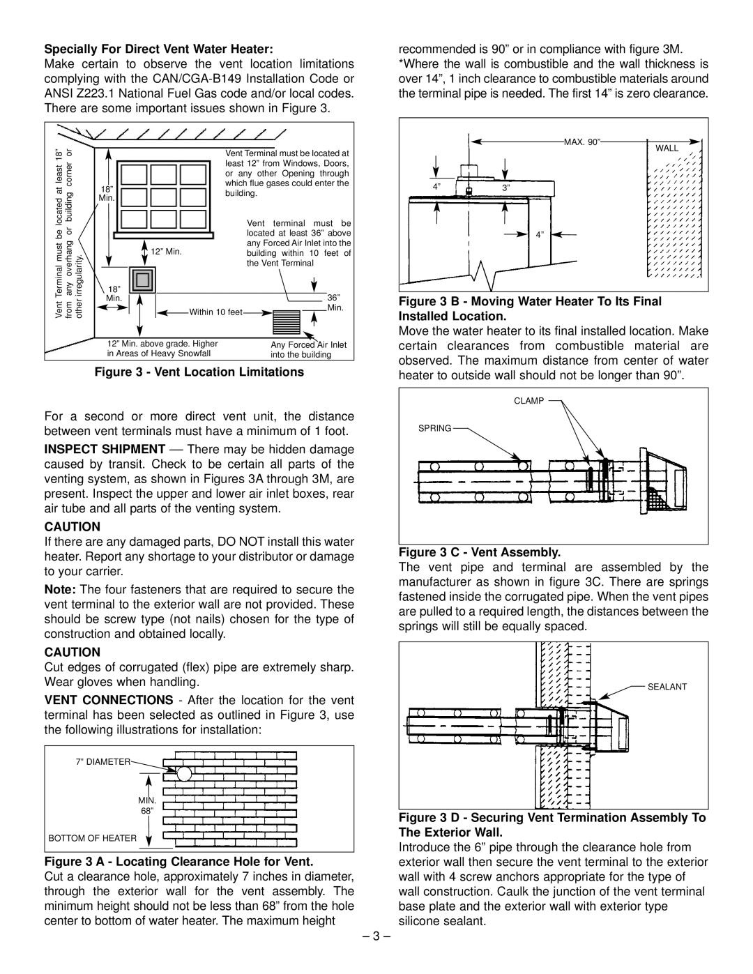
Make certain to observe the vent location limitations complying with the CAN/CGA-B149 Installation Code or ANSI Z223.1 National Fuel Gas code and/or local codes. There are some important issues shown in Figure 3.

recommended is 90” or in compliance with figure 3M. *Where the wall is combustible and the wall thickness is over 14”, 1 inch clearance to combustible materials around the terminal pipe is needed. The first 14” is zero clearance.

18” or

least

corner

located at

building

be or

Terminalmust

overhang irregularity.

Vent Terminal must be located at least 12” from Windows, Doors, or any other Opening through which flue gases could enter the

18”building. Min.

Vent terminal must be located at least 36” above any Forced Air Inlet into the

12” Min.building within 10 feet of the Vent Terminal

MAX. 90”

4”3”

4”

WALL

any

Vent from other

18”


36”

Min.


Min.


Within 10 feet


12” Min. above grade. Higher

Any Forced Air Inlet

in Areas of Heavy Snowfall

into the building

Figure 3 - Vent Location Limitations

Figure 3 B - Moving Water Heater To Its Final Installed Location.

Move the water heater to its final installed location. Make certain clearances from combustible material are observed. The maximum distance from center of water heater to outside wall should not be longer than 90”.

For a second or more direct vent unit, the distance between vent terminals must have a minimum of 1 foot.

INSPECT SHIPMENT –– There may be hidden damage caused by transit. Check to be certain all parts of the venting system, as shown in Figures 3A through 3M, are present. Inspect the upper and lower air inlet boxes, rear air tube and all parts of the venting system.

CAUTION

If there are any damaged parts, DO NOT install this water heater. Report any shortage to your distributor or damage to your carrier.

Note: The four fasteners that are required to secure the vent terminal to the exterior wall are not provided. These should be screw type (not nails) chosen for the type of construction and obtained locally.

CAUTION

Cut edges of corrugated (flex) pipe are extremely sharp. Wear gloves when handling.

VENT CONNECTIONS - After the location for the vent terminal has been selected as outlined in Figure 3, use the following illustrations for installation:

7” DIAMETER

MIN.

68”

BOTTOM OF HEATER

Figure 3 A - Locating Clearance Hole for Vent.

Cut a clearance hole, approximately 7 inches in diameter, through the exterior wall for the vent assembly. The minimum height should not be less than 68” from the hole center to bottom of water heater. The maximum height

– 3 –

CLAMP

SPRING

Figure 3 C - Vent Assembly.

The vent pipe and terminal are assembled by the manufacturer as shown in figure 3C. There are springs fastened inside the corrugated pipe. When the vent pipes are pulled to a required length, the distances between the springs will still be equally spaced.

SEALANT

Figure 3 D - Securing Vent Termination Assembly To The Exterior Wall.

Introduce the 6” pipe through the clearance hole from exterior wall then secure the vent terminal to the exterior wall with 4 screw anchors appropriate for the type of wall construction. Caulk the junction of the vent terminal base plate and the exterior wall with exterior type silicone sealant.

Page 4
Image 4
GSW PART NO.70999 REV.G (03-12) operating instructions Vent Location Limitations

PART NO.70999 REV.G (03-12) specifications

The GSW PART NO. 70999 REV.G (03-12) is an exemplary product designed for high-performance application in various industrial settings. This part stands out not only for its robust construction but also for its advanced technological features, which cater to the evolving demands of modern industry.

One of the main characteristics of the GSW 70999 REV.G is its durable design, engineered to withstand challenging operational conditions. The materials used in its construction are specifically chosen for their strength and resistance to wear and corrosion, ensuring longevity and reliability in performance. This makes the component an ideal choice for applications that require consistent and dependable operation over extended periods.

In terms of technology, the GSW 70999 REV.G incorporates cutting-edge manufacturing processes that enhance its precision and functionality. The advanced machining techniques employed ensure tight tolerances and superior fit, which contribute to improved efficiency in machinery operation. This precision is particularly critical in high-speed applications, where even minor discrepancies can lead to significant performance issues.

Another key feature of the GSW 70999 REV.G is its adaptability. The part is designed with versatility in mind, allowing it to be integrated seamlessly into a variety of systems and equipment. This adaptability minimizes downtime during installation and maintenance, as users can easily incorporate the part into their existing configurations without extensive modifications.

The GSW 70999 REV.G also benefits from innovative design aspects such as ergonomic considerations, which aim to simplify handling and improve user experience. The thoughtful layout and accessibility of the component facilitate easier maintenance procedures, ultimately reducing operational costs and maximizing productivity for users.

Furthermore, GSW emphasizes sustainability in its product design and manufacturing processes. The materials are selected not only for their performance characteristics but also for their environmental impact, aligning with the industry's growing focus on sustainability and responsible sourcing.

In summary, the GSW PART NO. 70999 REV.G (03-12) is a crucial component characterized by its durability, precision, adaptability, and commitment to sustainability. It serves as an integral part in various industrial applications, promoting efficiency and reliability while catering to the increasing demands of modern technological advancement. Whether in high-speed settings or more moderate environments, this part exemplifies quality and innovation in industrial design.