Section 1 — General Information
Guardian
•Install the transfer switch indoors on a firm, stur- dy supporting structure.
•To prevent switch distortion, level the switch if nec- essary. This can be done by placing washers between the switch enclosure and mounting sur- face.
•Never install the switch where water or any corro- sive substance might drip onto the enclosure.
•Protect the switch at all times against excessive moisture, dust, dirt, lint, construction grit and corrosive vapors.
1.11 BATTERY INSTALLATION
Fill the battery with the proper electrolyte fluid if nec- essary and have the battery fully charged before installing it.
Before installing and connecting the battery, complete the following steps:
1.Set the generator's AUTO/OFF/MANUAL switch to OFF.
2.Turn off utility power supply to the transfer switch.
3.Remove the 5A and 15A fuses from the generator control panel.
If the AUTO/OFF/MANUAL switch is not set to its OFF position, the generator can crank and start as soon as the battery cables are connect- ed. If the utility power supply is not turned off, sparking can occur at the battery posts and cause an explosion.
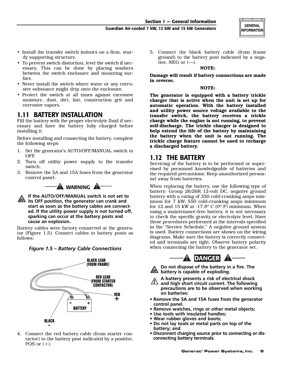
Battery cables were factory connected at the genera- tor (Figure 1.5). Connect cables to battery posts as follows:
Figure 1.5 – Battery Cable Connections
5.Connect the black battery cable (from frame ground) to the battery post indicated by a nega- tive, NEG or
NOTE:
Damage will result if battery connections are made in reverse.
NOTE:
The generator is equipped with a battery trickle charger that is active when the unit is set up for automatic operation. With the battery installed and utility power source voltage available to the transfer switch, the battery receives a trickle charge while the engine is not running, to prevent
1.12 THE BATTERY
Servicing of the battery is to be performed or super- vised by personnel knowledgeable of batteries and the required precautions. Keep unauthorized person- nel away from batteries.
When replacing the battery, use the following type of battery: Group 26/26R
4.Connect the red battery cable (from starter con- tactor) to the battery post indicated by a positive, POS or (+).
![]()
![]() DANGER
DANGER
Do not dispose of the battery in a fire. The battery is capable of exploding.
A battery presents a risk of electrical shock and high short circuit current. The following precautions are to be observed when working on batteries:
•Remove the 5A and 15A fuses from the generator control panel.
•Remove watches, rings or other metal objects;
•Use tools with insulated handles;
•Wear rubber gloves and boots;
•Do not lay tools or metal parts on top of the battery; and
•Disconnect charging source prior to connecting or dis- connecting battery terminals.
Generac® Power Systems, Inc. 9