Section 4 — Maintenance
Guardian
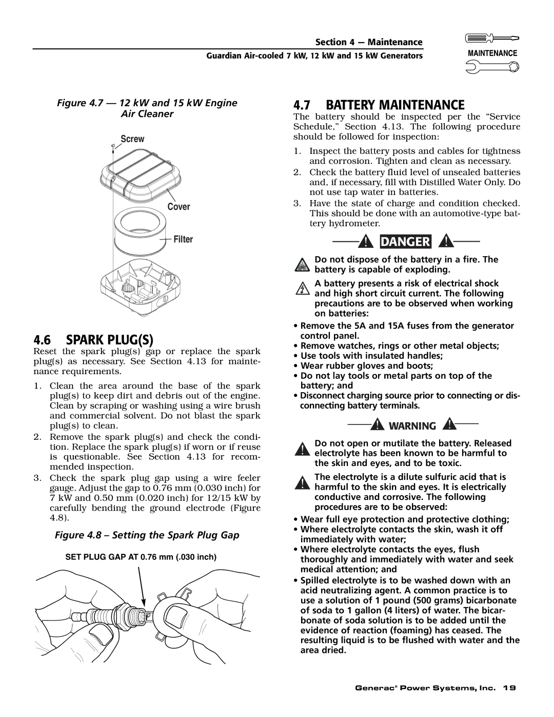
Figure 4.7 — 12 kW and 15 kW Engine
Air Cleaner
Screw
Cover
4.7BATTERY MAINTENANCE
The battery should be inspected per the “Service Schedule,” Section 4.13. The following procedure should be followed for inspection:
1.Inspect the battery posts and cables for tightness and corrosion. Tighten and clean as necessary.
2.Check the battery fluid level of unsealed batteries and, if necessary, fill with Distilled Water Only. Do not use tap water in batteries.
3.Have the state of charge and condition checked. This should be done with an
Filter | DANGER |
4.6SPARK PLUG(S)
Reset the spark plug(s) gap or replace the spark plug(s) as necessary. See Section 4.13 for mainte- nance requirements.
1.Clean the area around the base of the spark plug(s) to keep dirt and debris out of the engine. Clean by scraping or washing using a wire brush and commercial solvent. Do not blast the spark plug(s) to clean.
2.Remove the spark plug(s) and check the condi- tion. Replace the spark plug(s) if worn or if reuse is questionable. See Section 4.13 for recom- mended inspection.
3.Check the spark plug gap using a wire feeler gauge. Adjust the gap to 0.76 mm (0.030 inch) for 7 kW and 0.50 mm (0.020 inch) for 12/15 kW by carefully bending the ground electrode (Figure 4.8).
Figure 4.8 – Setting the Spark Plug Gap
SET PLUG GAP AT 0.76 mm (.030 inch)
Do not dispose of the battery in a fire. The battery is capable of exploding.
A battery presents a risk of electrical shock and high short circuit current. The following precautions are to be observed when working on batteries:
•Remove the 5A and 15A fuses from the generator control panel.
•Remove watches, rings or other metal objects;
•Use tools with insulated handles;
•Wear rubber gloves and boots;
•Do not lay tools or metal parts on top of the battery; and
•Disconnect charging source prior to connecting or dis- connecting battery terminals.
Do not open or mutilate the battery. Released
!electrolyte has been known to be harmful to the skin and eyes, and to be toxic.
The electrolyte is a dilute sulfuric acid that is
!harmful to the skin and eyes. It is electrically conductive and corrosive. The following procedures are to be observed:
•Wear full eye protection and protective clothing;
•Where electrolyte contacts the skin, wash it off immediately with water;
•Where electrolyte contacts the eyes, flush thoroughly and immediately with water and seek medical attention; and
•Spilled electrolyte is to be washed down with an acid neutralizing agent. A common practice is to use a solution of 1 pound (500 grams) bicarbonate of soda to 1 gallon (4 liters) of water. The bicar- bonate of soda solution is to be added until the evidence of reaction (foaming) has ceased. The resulting liquid is to be flushed with water and the area dried.
Generac® Power Systems, Inc. 19