Section 3 — Operation
Guardian
NOTE:
The access panel on top of the control panel must be removed to adjust the voltage regulator.
NOTE:
3.2USING THE AUTO/OFF/MANUAL SWITCH (FIGURE 3.1)
3.2.1 “AUTO” POSITION
The voltage regulator is housed above the genera- tor's control panel. The regulator maintains a volt- age in direct proportion to frequency at a
Selecting this switch position activates fully automat- ic system operation. It also allows personnel to start and exercise the engine every seven days with the set- ting of the exercise timer (see Section 3.6). This posi- tion also is used for remote starting, when it is set up.
3.1BREAK-IN PROCEDURE
Once the unit has been installed and all electrical checks have been made, it is strongly recommended that the following
1. | Set the generator’s AUTO/OFF/MANUAL switch to |
| AUTO. |
2. | Turn OFF the utility power supply to the transfer |
| switch using the means provided (such as a utili- |
| ty main line circuit breaker). |
3. | The unit will start, and the transfer switch will |
| transfer to standby. |
3.2.2 “OFF” POSITION
This switch position shuts down the engine. This position also prevents automatic operation.
3.2.3 “MANUAL” POSITION
Set the switch to MANUAL to crank and start the engine. Transfer to standby power will not occur unless there is a utility failure.
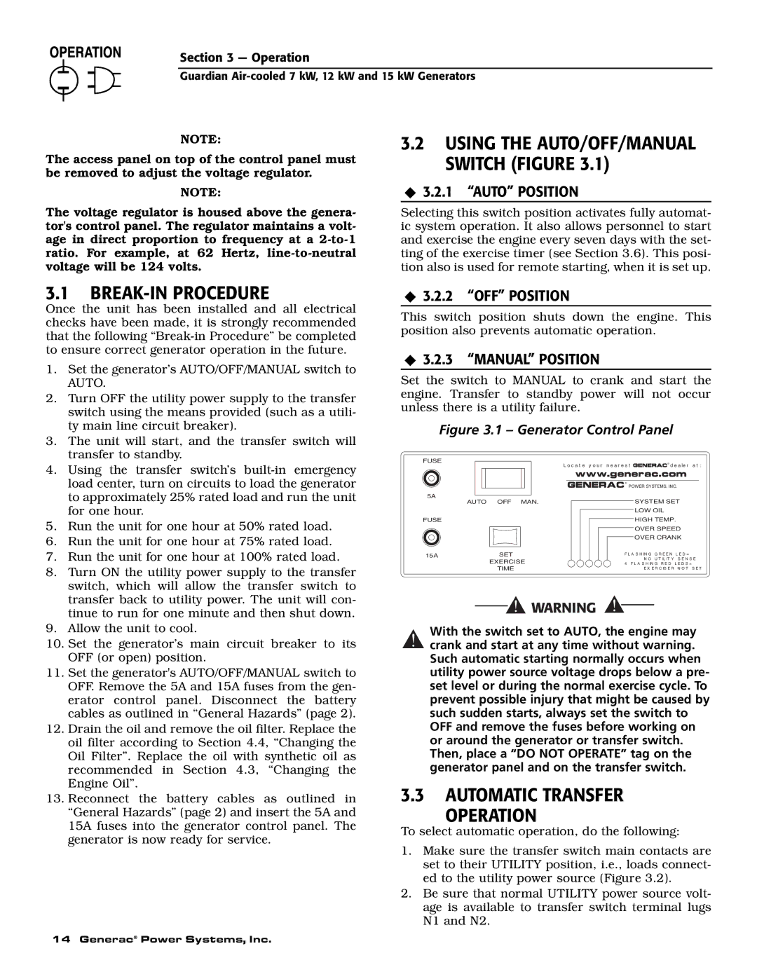
Figure 3.1 – Generator Control Panel
4. | Using the transfer switch’s |
| load center, turn on circuits to load the generator |
| to approximately 25% rated load and run the unit |
| for one hour. |
5. | Run the unit for one hour at 50% rated load. |
6. | Run the unit for one hour at 75% rated load. |
7. | Run the unit for one hour at 100% rated load. |
8. | Turn ON the utility power supply to the transfer |
| switch, which will allow the transfer switch to |
| transfer back to utility power. The unit will con- |
| tinue to run for one minute and then shut down. |
FUSE
5A
AUTO OFF MAN.
FUSE
15ASET EXERCISE
TIME
L o c a t e y o u r n e a r e s t ![]()
![]()
![]() d e a le r a t :
d e a le r a t :
![]() POWER SYSTEMS, INC.
POWER SYSTEMS, INC.
SYSTEM SET
LOW OIL
HIGH TEMP.
OVER SPEED
OVER CRANK
F L A S H IN G G R E E N L E D =
N O U T IL IT Y S E N S E 4 F L A S H IN G R E D L E D S =
E X E R C IS E R N O T S E T
9. | Allow the unit to cool. |
10. | Set the generator’s main circuit breaker to its |
| OFF (or open) position. |
11. | Set the generator's AUTO/OFF/MANUAL switch to |
| OFF. Remove the 5A and 15A fuses from the gen- |
| erator control panel. Disconnect the battery |
| cables as outlined in “General Hazards” (page 2). |
12. | Drain the oil and remove the oil filter. Replace the |
| oil filter according to Section 4.4, “Changing the |
| Oil Filter”. Replace the oil with synthetic oil as |
| recommended in Section 4.3, “Changing the |
| Engine Oil”. |
13. | Reconnect the battery cables as outlined in |
| “General Hazards” (page 2) and insert the 5A and |
| 15A fuses into the generator control panel. The |
| generator is now ready for service. |
14 Generac® Power Systems, Inc.
With the switch set to AUTO, the engine may
!crank and start at any time without warning. Such automatic starting normally occurs when utility power source voltage drops below a pre- set level or during the normal exercise cycle. To prevent possible injury that might be caused by such sudden starts, always set the switch to OFF and remove the fuses before working on or around the generator or transfer switch. Then, place a “DO NOT OPERATE” tag on the generator panel and on the transfer switch.
3.3AUTOMATIC TRANSFER
OPERATION
To select automatic operation, do the following:
1.Make sure the transfer switch main contacts are set to their UTILITY position, i.e., loads connect- ed to the utility power source (Figure 3.2).
2.Be sure that normal UTILITY power source volt- age is available to transfer switch terminal lugs N1 and N2.