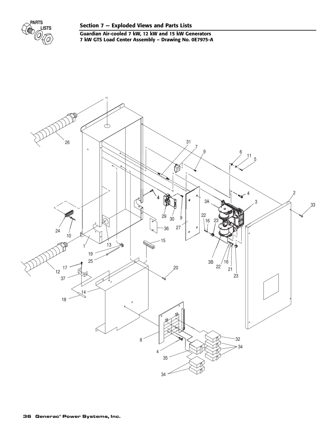
Not intended for use as Primary Power in place of utility or
DEADLY EXHAUST FUMES. OUTDOOR INSTALLATION ONLY
This manual should remain with the unit
POWER SYSTEMS
HOW TO OBTAIN SERVICE
CONTENTS
OPERATION AND MAINTENANCE
INTRODUCTION
Safety Rules
Table of Contents
Despite the safe design of this generator
GENERAL HAZARDS
DANGER
Parts of the generator are rotating and/or hot
EXPLOSION HAZARDS
ELECTRICAL HAZARDS
FIRE HAZARDS
STANDARDS INDEX
1.2 PROTECTION SYSTEMS
1.3.1 SECTION 210.12 ARC FAULT CIRCUIT INTERRUPTER PROTECTION
1.1 UNPACKING/INSPECTION
BREAKER FOR BEDROOMS
Figure 1.2 - 12 kW and 15 kW, V-twin GT-990 Engine
1.4 THE GENERATOR
Figure 1.1 - 7 kW, Single Cylinder GH-410 Engine
1.5.2 ENGINE
1.5 SPECIFICATIONS
1.5.1 GENERATOR
Section 1 - General Information
1.7 FUEL REQUIREMENTS AND RECOMMENDATIONS
1.9 RECONFIGURING THE FUEL SYSTEM
1.6 SYSTEM SET LED
1.8 FUEL CONSUMPTION
1.9.2 12KW AND 15KW, 990CC ENGINES
1.10.2 TRANSFER SWITCH 1.10.2.1 7 kW, 12 kW and 15 kW Units
1.10 LOCATION
1.10.1 GENERATOR
Figure 1.5 - Battery Cable Connections
1.11 BATTERY INSTALLATION
1.12 THE BATTERY
Use tools with insulated handles Wear rubber gloves and boots
2.3 ELECTRICAL CHECKS
2.2 CHECK TRANSFER SWITCH OPERATION
2.1 BEFORE INITIAL START-UP
Do not open or mutilate the battery. Released
DANGER
2.4 GENERATOR TESTS UNDER LOAD
2.5 CHECKING AUTOMATIC OPERATION
Figure 2.1 - Dual Fuel Regulators
2.6 ADJUSTING THE REGULATOR NATURAL GAS ONLY
Figure 2.2 - Placement of Regulator
Do not make any unnecessary adjustments
Figure 2.3 - Engine Governor Adjustment
2.7 ENGINE GOVERNOR ADJUSTMENT
2.8 VOLTAGE REGULATOR ADJUSTMENT
Figure 2.4 - Full Load Speed Adjust Screw
3.3 AUTOMATIC TRANSFER OPERATION
3.1 BREAK-IN PROCEDURE
3.2 USING THE AUTO/OFF/MANUAL SWITCH FIGURE
3.2.1 “AUTO” POSITION
3.5 MANUAL TRANSFER OPERATION
Figure 3.2 - Manual Transfer Switch Operation
3.5.1 TRANSFER TO GENERATOR POWER SOURCE
3.4 SEQUENCE OF AUTOMATIC OPERATION
3.7.1 LOW OIL PRESSURE SWITCH
3.6 SETTING THE EXERCISE TIMER
3.5.2 TRANSFER BACK TO UTILITY POWER SOURCE
3.7.2 HIGH TEMPERATURE SWITCH
3.7.4 OVERSPEED
4.2 CHECKING THE ENGINE OIL LEVEL
3.7.3.1 Approximate Crank Cycle Times
Figure 4.2 - Oil Dipstick and Fill, 7 kW
Figure 4.6 - 7 kW, Engine Air Cleaner Location
4.5 CHANGING THE ENGINE AIR CLEANER
4.3.2 OIL CHANGE PROCEDURE
4.3 CHANGING THE ENGINE OIL
Figure 4.8 - Setting the Spark Plug Gap
4.7 BATTERY MAINTENANCE
Figure 4.7 - 12 kW and 15 kW Engine Air Cleaner
4.6 SPARK PLUGS
4.9 COOLING SYSTEM
4.8 ADJUSTING GH-410/GT-990 VALVE CLEARANCE
Figure 4.10 - Valve Clearance Adjustment
Figure 4.9 - Cooling Vent Locations
4.12.2 RETURN TO SERVICE
4.12 OUT OF SERVICE PROCEDURE
4.12.1 REMOVAL FROM SERVICE
4.10 ATTENTION AFTER SUBMERSION
be performed by the nearest Guardian Authorized Dealer
4.13 SERVICE SCHEDULE
ATTENTION It is recommended that all service work
CAUSE
5.1 TROUBLESHOOTING GUIDE
PROBLEM
CORRECTION
Section 6 - Electrical Data
24 Generac Power Systems, Inc
ENGINE WIRING
CONTROL PANEL BOX
Generac Power Systems, Inc
Section 6 - Electrical Data
CUSTOMER
Section 6 - Electrical Data
Electrical Schematic - 12 & 15 kW - Drawing No. 0D8501-B
26 Generac Power Systems, Inc
Guardian Air-cooled 7 kW, 12 kW and 15 kW Generators
Section 6 - Electrical Data
Electrical Schematic - 12 & 15 kW - Drawing No. 0D8501-B
Generac Power Systems, Inc
Guardian Air-cooled 7 kW, 12 kW and 15 kW Generators
Section 6 - Electrical Data
28 Generac Power Systems, Inc
ENGINE WIRING
CONTROL PANEL BOX
Generac Power Systems, Inc
Section 6 - Electrical Data
CUSTOMER
Section 6 - Electrical Data
Electrical Schematic - 7 kW - Drawing No. 0D9014-C
30 Generac Power Systems, Inc
Guardian Air-cooled 7 kW, 12 kW and 15 kW Generators
Section 6 - Electrical Data
Electrical Schematic - 7 kW - Drawing No. 0D9014-C
Generac Power Systems, Inc
Guardian Air-cooled 7 kW, 12 kW and 15 kW Generators
9115
Section 7 - Exploded Views and Parts Lists
32 Generac Power Systems, Inc
DESCRIPTION
Section 7 - Exploded Views and Parts Lists
DESCRIPTION
Guardian Air-cooled 7 kW, 12 kW and 15 kW Generators
Section 7 - Exploded Views and Parts Lists
34 Generac Power Systems, Inc
Control Panel - Drawing No. 0E7974-B
ASSEMBLY, BATTERY CHARGER ENGINE
Section 7 - Exploded Views and Parts Lists
HARNESS, CONTROL PANEL WIRE NOT
ASSEMBLY, ROOF/DOOR GROUND WIRE
Section 7 - Exploded Views and Parts Lists
36 Generac Power Systems, Inc
Section 7 - Exploded Views and Parts Lists
DESCRIPTION
38 Generac Power Systems, Inc
Section 7 - Exploded Views and Parts Lists
12 kW and 15 kW GTS Load Center Assembly - Drawing No. 0E7973-B
Guardian Air-cooled 7 kW, 12 kW and 15 kW Generators
Section 7 - Exploded Views and Parts Lists
DESCRIPTION
5, 19, 20, 39, 40
Section 7 - Exploded Views and Parts Lists
40 Generac Power Systems, Inc
32, 33, 34
ASSEMBLY, HOUSING COVER WITH
Section 7 - Exploded Views and Parts Lists
ASSEMBLY, DIPSTICK WITH HANDLE
ASSEMBLY, CRANKCASE HOUSING WITH
42 Generac Power Systems, Inc
DESCRIPTION
Section 7 - Exploded Views and Parts Lists
DESCRIPTION
Guardian Air-cooled 7 kW, 12 kW and 15 kW Generators
Section 7 - Exploded Views and Parts Lists
44 Generac Power Systems, Inc
7 kW Generator - Drawing No. 0D3504-C
1.8 FT
Section 7 - Exploded Views and Parts Lists
DESCRIPTION
1.25 FT
Guardian Air-cooled 7 kW, 12 kW and 15 kW Generators
Section 7 - Exploded Views and Parts Lists
46 Generac Power Systems, Inc
12 kW and 15 kW Generator - Drawing No. 0D3417-H
2.6 FT
Section 7 - Exploded Views and Parts Lists
DESCRIPTION
3 FT
Section 7 - Exploded Views and Parts Lists
48 Generac Power Systems, Inc
Section 7 - Exploded Views and Parts Lists
DESCRIPTION
Section 7 - Exploded Views and Parts Lists
50 Generac Power Systems, Inc
Section 7 - Exploded Views and Parts Lists
DESCRIPTION
DESCRIPTION
Section 7 - Exploded Views and Parts Lists
PART NO. QTY
PART NO. QTY
ALL DIMENSIONS IN MILLIMETERS INCHES
Section 8 - Mounting Dimensions
Generac Power Systems, Inc
cooled 7 kW, 12 kW and 15 kW Generators Drawing No. 0D3739-B
54 Generac Power Systems, Inc
Guardian Air-cooled 7 kW, 12 kW and 15 kW Generators
Generac Power Systems, Inc
Guardian Air-cooled 7 kW, 12 kW and 15 kW Generators
PURCHASER’S/OWNER’S WARRANTY RESPONSIBILITIES
YOUR WARRANTY RIGHTS AND OBLIGATIONS
MANUFACTURER’S EMISSION CONTROL SYSTEM WARRANTY COVERAGE
CALIFORNIA EMISSION CONTROL WARRANTY STATEMENT
Section 10 - Warranty
EMISSION CONTROL SYSTEM WARRANTY
EMISSION RELATED PARTS INCLUDE THE FOLLOWING
Section 10 - Warranty
GENERAC POWER SYSTEMS “TWO YEAR” LIMITED WARRANTY FOR GUARDIAN
“PREPACKAGED EMERGENCY AUTOMATIC STANDBY GENERATORS”
WARRANTY SCHEDULE