INSTALLATION
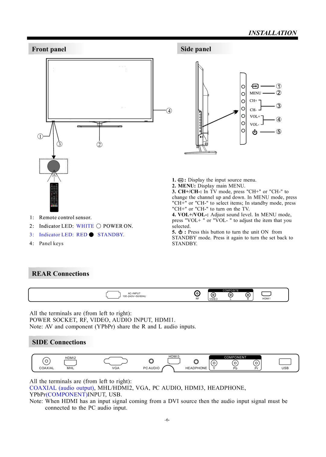
Front panel |
| Side panel | ||
|
|
|
|
|
|
|
|
|
|
4
1
32
| 30 | 30 |
| 1. | : Display the input source menu. | |
|
|
|
| |||
|
|
|
| 2. | MENU: Display main MENU. | |
|
|
|
| 3. | ||
|
|
|
| change the channel up and down. In MENU mode, press | ||
|
|
|
| "CH+" or | ||
|
|
|
| "CH+" or | ||
1: | Remote control sensor. |
| 4. | |||
| press "VOL+ " or "VOL- " to adjust the item that you | |||||
2: | Indicator LED: WHITE | POWER ON. | ||||
selected. | ||||||
3: | Indicator LED: RED | STANDBY. | 5. | : Press this button to turn the unit ON from | ||
STANDBY mode. Press it again to turn the set back to | ||||||
4: | Panel keys |
| ||||
| STANDBY. | |||||
REAR Connections
COMPOSITE
RF | VIDEO | L | R | HDMI1 |
All the terminals are (from left to right):
POWER SOCKET, RF, VIDEO, AUDIO INPUT, HDMI1.
Note: AV and component (YPbPr) share the R and L audio inputs.
SIDE Connections
HDMI2
COAXIAL | MHL | VGA | PC AUDIO |
HDMI3 | COMPONENT |
|
|
HEADPHONE Y | Pb | Pr | USB |
All the terminals are (from left to right):
COAXIAL (audio output), MHL/HDMI2, VGA, PC AUDIO, HDMI3, HEADPHONE, YPbPr(COMPONENT)INPUT, USB.
Note: When HDMI has an input signal coming from a DVI source then the audio input signal must be connected to the PC audio input.